

Femur Supporting Device
a supporting device and femur technology, applied in the field of femur supporting devices, can solve the problems of high operation risk, patient needs a longer recovery time, and the operation wound cannot be reduced, so as to save the operation time, save the operation risk, and save the effect of most bone tissues
- Summary
- Abstract
- Description
- Claims
- Application Information
AI Technical Summary
Benefits of technology
Problems solved by technology
Method used
Image

Examples
Embodiment Construction
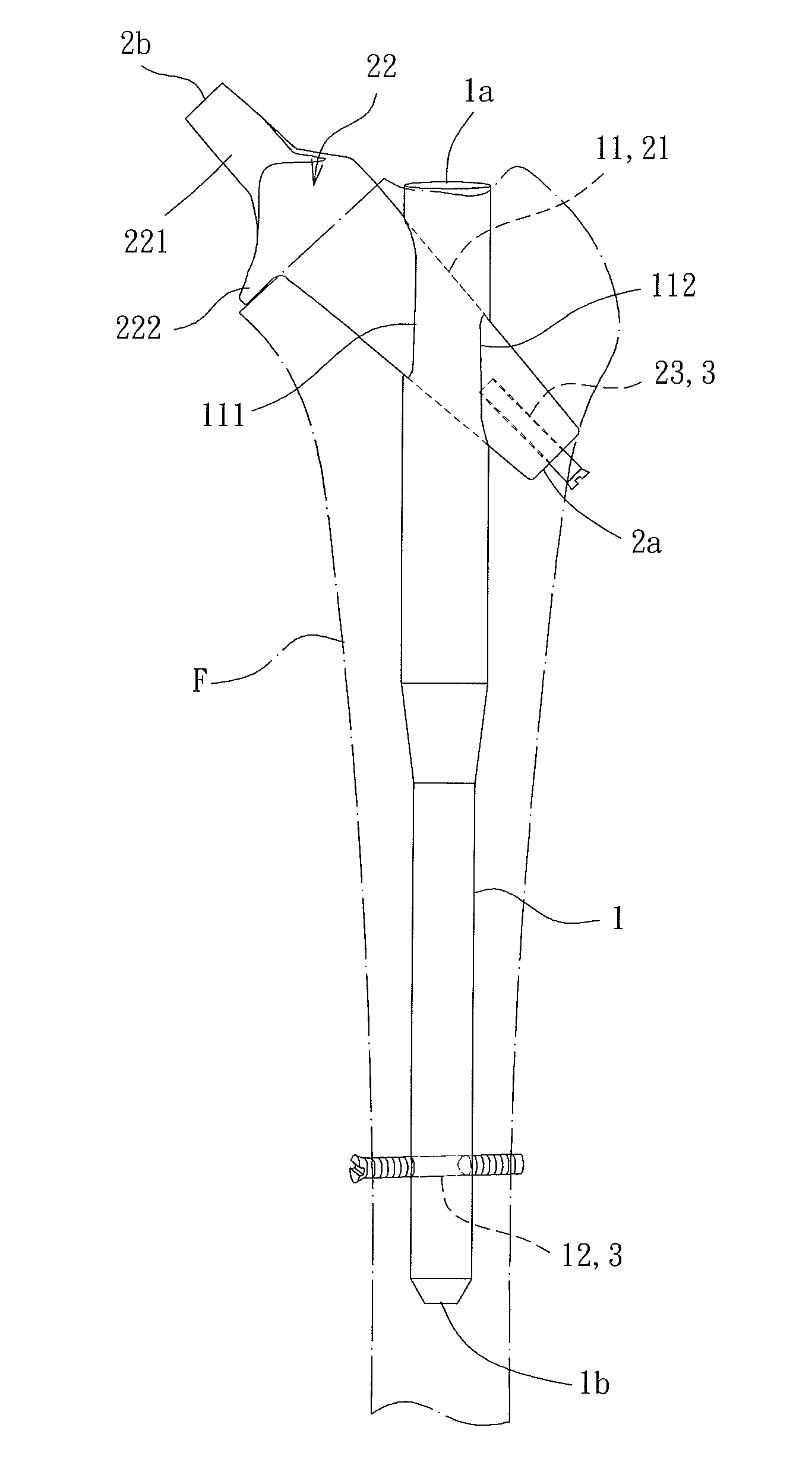
[0032]With reference to FIGS. 3 and 4, a femur supporting device according to the present invention includes a rod 1, an insert 2, and a fastener 3. The rod 1 can be longitudinally implanted into a medullary cavity of a femur F of a patient. The insert 2 is engaged with the rod 1 and is adapted to couple with an artificial femoral head. The fastener 3 extends from a side of the femur F through the other side of the femur F to fix the rod 1.
[0033]The rod 1 includes a head end 1a and an implant end 1b spaced from the head end 1a along a longitudinal axis. The rod 1 is implanted into the medullary cavity of the femur F through the implant end 1b. The rod 1 includes an insertion groove 11 extending through an outer periphery of the rod 1 and having an inlet 111 and an outlet 112 aligned with the inlet 111, allowing insertion and engagement of the insert 2. In this embodiment, the insertion groove 11 has decreasing cross sectional widths from the inlet 111 towards the outlet 112 to secur...
PUM
 Abstract
Description
Claims
Application Information