Self-propelled stall cleaning apparatus

Active Publication Date: 2014-07-03
CLARK LOUISE KLEMM
View PDF20 Cites 27 Cited by
  • Summary
  • Abstract
  • Description
  • Claims
  • Application Information

AI Technical Summary

Benefits of technology

[0012]The self-propelled stall cleaning apparatus further has a collection bin positioned at the rearward elevated location below the lift conveyor. The collection bin has sides, two of the sides each have a curved guide track affixed. The collection bin is attached to the frame by at least one roller affixed to each side of the frame. The roller is in the guide tracks and the bin is movable from a low stowed position upwardly along the guide tracks to a tilted debris dumping position. Preferably, the bin is attached or rests on a movable platform. The self-propelled stall cleaning apparatus further has a means for lifting the bin. The means for lifting the bins is one of either hydraulic or pneumatic cylinders or a motor

Problems solved by technology

When the animal droppings accumulate, the bedding material is often rendered useless.
Cleaning stalls typically is a manual effort involving labor intensive use of pitch forks and wheel barrows.
In these situations, the amount of manure removed can be very large and the work extremely fatiguing.
The appa

Method used


Image

  • Self-propelled stall cleaning apparatus
  • Self-propelled stall cleaning apparatus
  • Self-propelled stall cleaning apparatus

Examples


Embodiment Construction

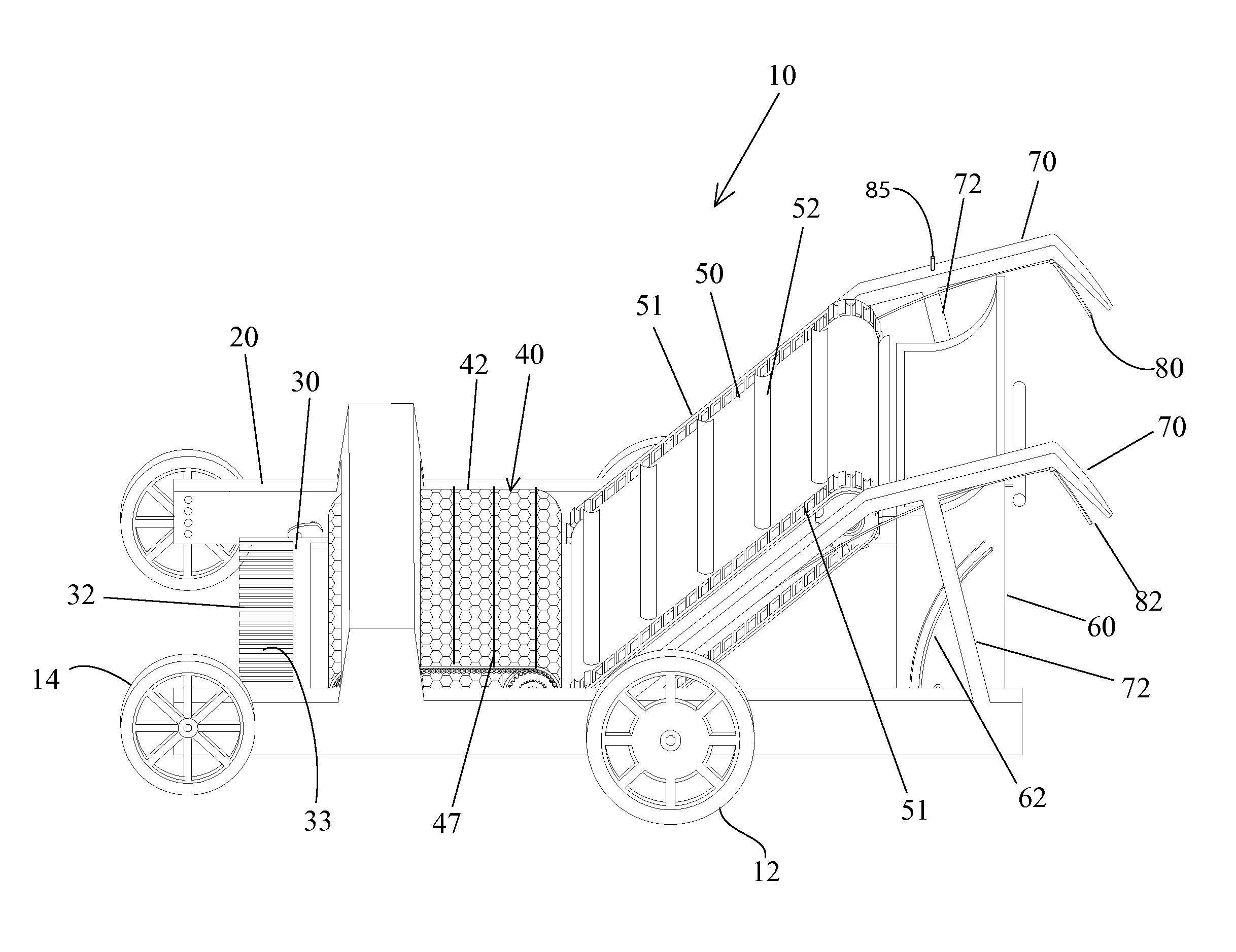
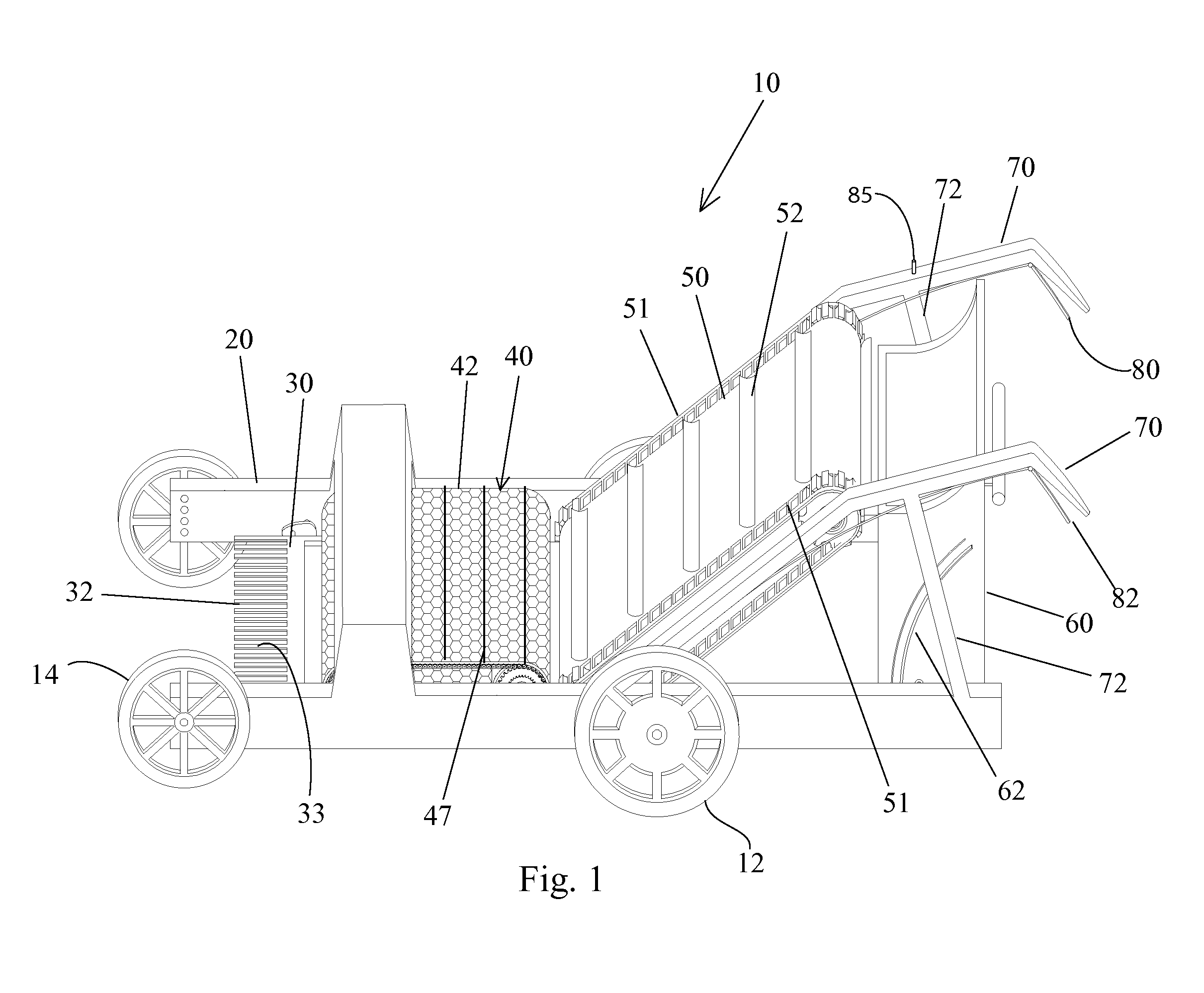
[0023]With reference to FIG. 1, a perspective view of the present invention is shown. As illustrated, a stall cleaning apparatus 10 is shown. In the preferred embodiment, the stall cleaning apparatus 10 has a frame assembly 20 to which various mechanisms are attached. As shown in FIG. 1, the apparatus 10 has four wheels, two rear wheels 12 are driven by a motor 100, the forward wheels 14 are provided for stability and steering support. It is possible to design the apparatus with only two large drive wheels 12. If so constructed, the drive wheels 12 are positioned in such an orientation that they would move slightly forward to provide a center of gravity support for the entire apparatus 10. It is believed preferable however, that the device be made with four wheels as illustrated. With reference to the forward end of the apparatus 10 is shown a motor driven collector head 30. The collector head 30 has a pivoting fork 32 as shown. This fork 32 has tines 33 for collecting manure and ot...


PUM


Abstract

A self-propelled stall cleaning apparatus has a frame assembly, one pair of drive wheels, a motor attached to the assembly for driving the drive wheels and a motor driven collector head. The collector head has a pivoting fork with tines for collecting manure and debris. The fork picks up the manure and debris and tosses it onto a sifting conveyor. The sifting conveyor separates the manure from the bedding and delivers the manure to a lift conveyor which drops the manure into a collection bin. The collection bin is moveable from a stowed position to a dumping position.

Description

FIELD OF THE INVENTION[0001]This invention relates to a self-propelled stall cleaning apparatus.BACKGROUND OF THE INVENTION[0002]Bedding material used in animal stalls has to be periodically removed and replaced. Such bedding material can be made of wood shavings, straw or other suitable materials. Often the stalls have dirt floors, typically made of clay, soil or even concrete floors typically with rubber mats onto which the bedding is laid.[0003]When the animal droppings accumulate, the bedding material is often rendered useless. However, properly maintained mucking of stalls has enabled the bedding material to last over more extended periods of time.[0004]Cleaning stalls typically is a manual effort involving labor intensive use of pitch forks and wheel barrows.[0005]When cleaning a single stall, this method is very reliable and reasonably efficient. In larger horse farms, this chore may involve cleaning many stalls often 20 or 30 or more. In these situations, the amount of manur...

Claims


Application Information

Patent Timeline
IPC IPC(8): A01K1/01
CPCA01K1/015A01K1/0146A01K1/01A01G20/43A01B43/00
Inventor CLARK, LOUISE KLEMM
Owner CLARK LOUISE KLEMM
Why Eureka
Try Eureka