
Measurement apparatus and measurement method

a measurement apparatus and measurement method technology, applied in the direction of mechanical measuring arrangements, instruments, using mechanical means, etc., can solve the problems of cumbersome operation, difficult for an unexperienced operator, and the inability to move the measuring head

Inactive Publication Date: 2014-07-03
CANON KK
View PDF8 Cites 16 Cited by
  • Summary
  • Abstract
  • Description
  • Claims
  • Application Information

AI Technical Summary

Benefits of technology

The present invention provides a measurement apparatus that can automatically measure the shape of an object. The apparatus has a measuring head that can perform measurement in two modes: a first mode with lower accuracy and a second mode with higher accuracy. The apparatus can detect the region where the object is located and move the measuring head accordingly to ensure accurate measurement. This allows for efficient and automated measurement.

Problems solved by technology

This operation is cumbersome and is difficult for an unexperienced operator.
In automatic measurement described in non-patent literature 1, the measuring head may collide against the object to be measured, which imposes a limitation that the measuring head cannot be moved until the object to be measured is completely specified.
Therefore, there is no problem if it is possible to specify the object to be measured by preliminary measurement but it may be impossible to specify the object to be measured due to the presence of a blind spot depending on the shape and arrangement of the object to be measured.
Furthermore, if an object detection range for specifying the object to be measured is narrowed to allow a blind spot to some extent, the object to be measured may be erroneously specified and thus the measuring head may collide against the object to be measured.

Method used


Image

  • Measurement apparatus and measurement method
  • Measurement apparatus and measurement method
  • Measurement apparatus and measurement method

Examples


first embodiment

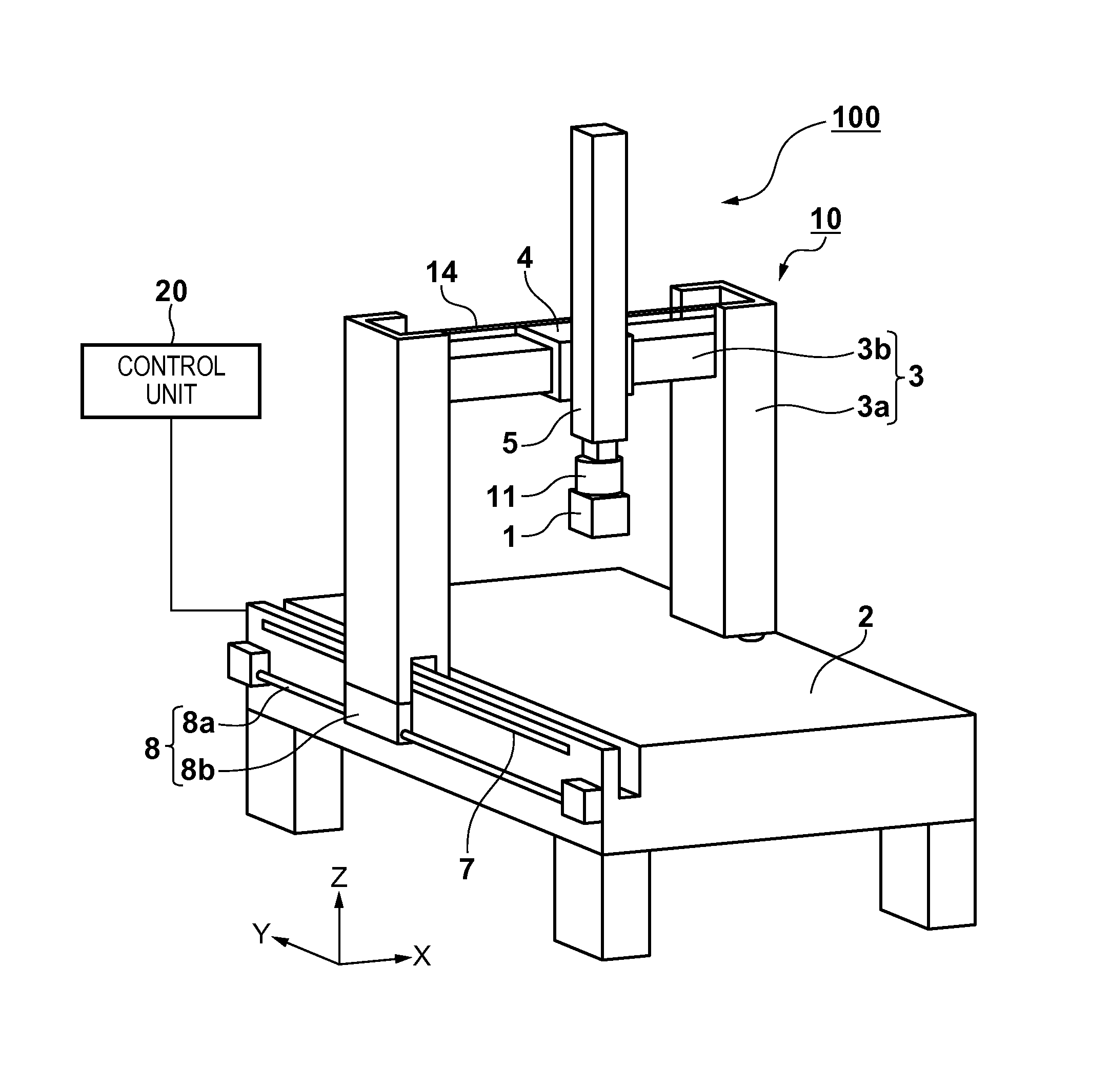
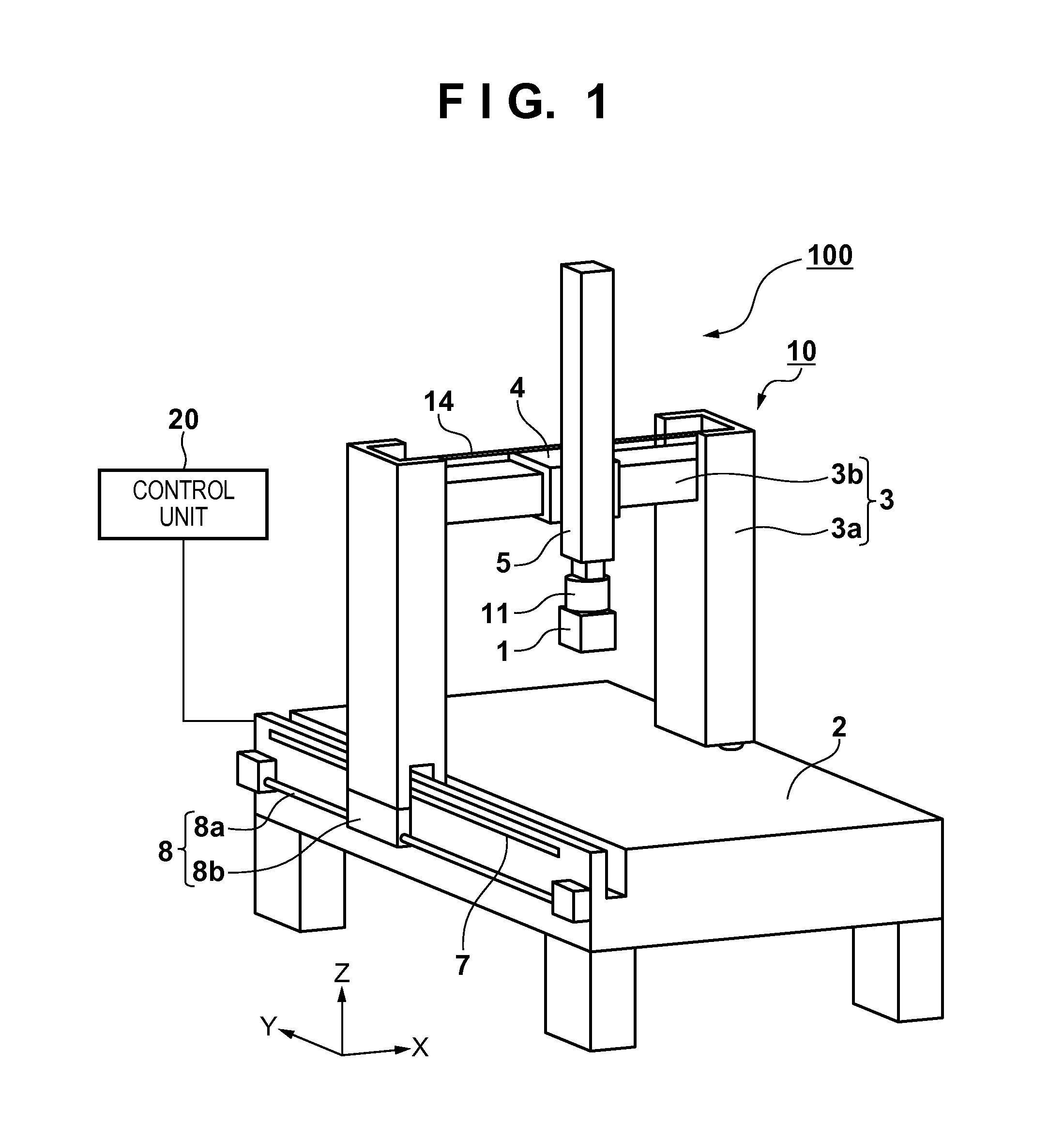
[0030]A measurement apparatus 100 according to the first embodiment of the present invention will be described with reference to FIG. 1. FIG. 1 is a view showing the measurement apparatus 100 according to the first embodiment. The measurement apparatus 100 according to the first embodiment includes a measuring head 1 for measuring the shape of an object to be measured, a driving unit 10 for driving the measuring head 1, and a control unit 20 for controlling the measuring head 1 and the driving unit 10. The measurement apparatus 100 according to the first embodiment measures the shape of the object to be measured while moving the measuring head 1 along the surface (surface to be measured) of the object to be measured so that, for example, the distance between the measuring head 1 and the surface to be measured becomes constant. Note that movement will also be referred to as motion or shift and can include not only a change in position but also a change in attitude.

[0031]The arrangeme...

second embodiment

[0052]A measurement apparatus according to the second embodiment of the present invention will be described. In the first embodiment, to prevent the measuring head from colliding against the object to be measured when moving the measuring head 1 in preliminary measurement, the detection unit detects the arrangement of the object to be measured. In the second embodiment, instead of detecting the arrangement of an object to be measured, a measuring head 1 includes a collision preventing sensor 27 to prevent the measuring head 1 from colliding against (contacting) the object to be measured.

[0053]FIG. 9 shows the measuring head 1 including the collision preventing sensor 27. The collision preventing sensor 27 is a sensor for detecting the presence / absence of an object to be measured in the moving direction of the measuring head 1. If an object to be measured exists in this direction, for example, the sensor 27 can preferably measure the distance between the collision preventing sensor 2...

third embodiment

[0054]A measurement apparatus according to the third embodiment of the present invention will be described. The arrangement of a measuring head 1 of the measurement apparatus according to the third embodiment is different from that of the measurement apparatus 100 according to the first embodiment. In the third embodiment, therefore, the arrangement of the measuring head 1 will be explained with reference to FIGS. 10 to 12. The remaining components are the same as those of the measurement apparatus 100 according to the first embodiment and a description thereof will be omitted.

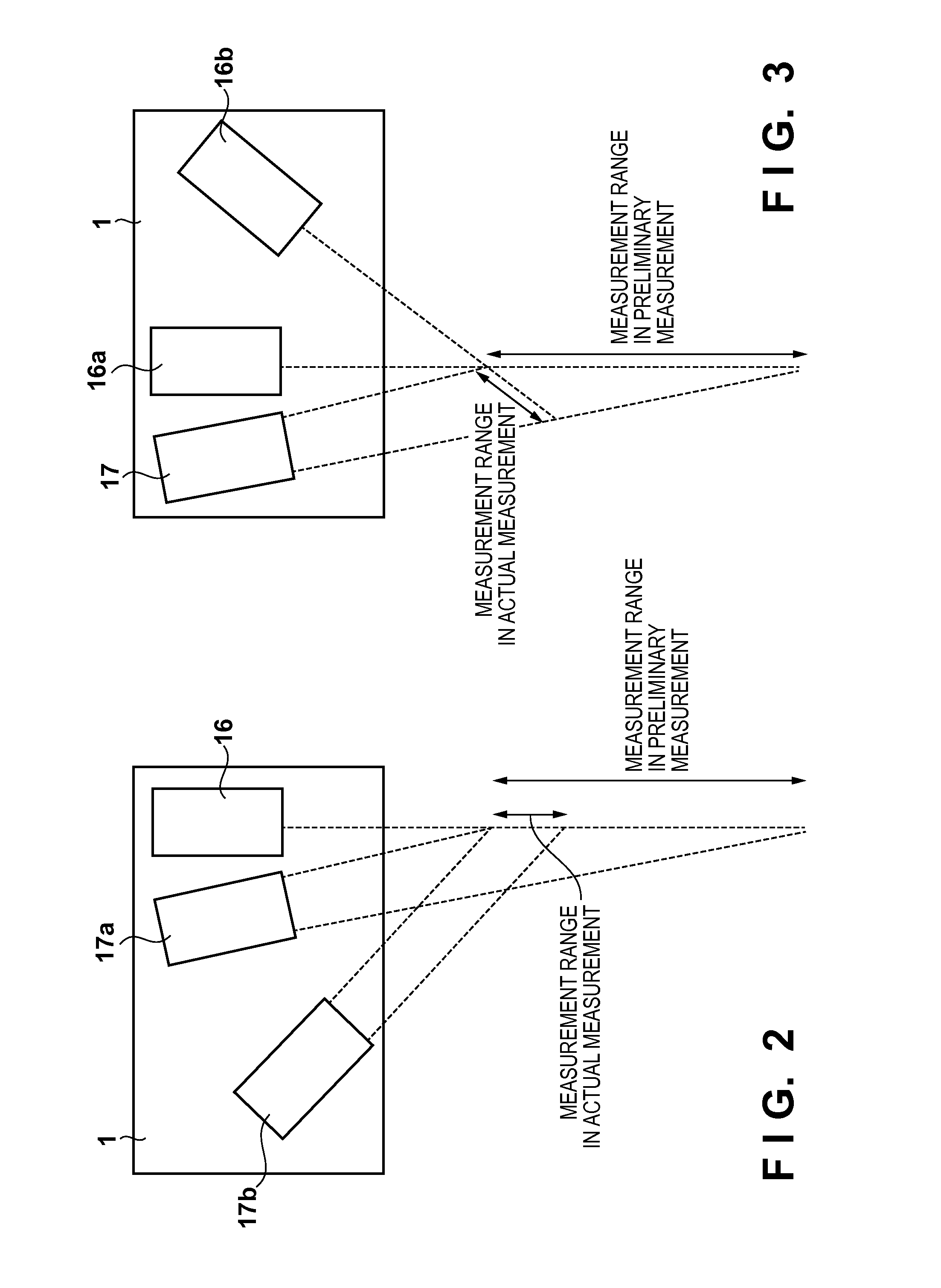
[0055]The arrangement of the measuring head 1 according to the third embodiment will be described with reference to FIGS. 10 to 12. In the third embodiment, a case in which the shape of an object to be measured is measured using a pattern projection method (two-dimension pattern projection type triangulation) will be explained. The pattern projection method is a method of acquiring height information of the ob...


PUM


Abstract

The present invention provides a measurement apparatus for measuring a shape of an object to be measured, comprising a measuring head configured to perform measurement in a first measurement mode and perform measurement in a second measurement mode having measurement accuracy higher than that of the first measurement mode, a detection unit configured to detect an occupancy region of the object to be measured, and a control unit configured to control the measuring head, wherein in the first measurement mode, the control unit moves, based on a detection result of the detection unit, the measuring head not to touch the object to be measured, and in the second measurement mode, the control unit moves, based on a measurement result in the first measurement mode, the measuring head to satisfy an allowable condition in the second measurement mode.

Description

BACKGROUND OF THE INVENTION[0001]1. Field of the Invention[0002]The present invention relates to a measurement apparatus and a measurement method.[0003]2. Description of the Related Art[0004]There is known a three-dimensional coordinate measurement apparatus (CMM: Coordinate Measuring Machine). The measurement apparatus includes a contact touch probe or non-contact optical probe on a measuring head, and measures coordinates on the surface of an object to be measured (the size and shape of an object to be measured) by moving the measuring head.[0005]To measure an object to be measured by such measurement apparatus, it is necessary to align the object to be measured with respect to the measurement apparatus before the start of measurement. To align the object, an operator needs to measure a plurality of reference positions (the positions of reference points) of the object to be measured by moving the measuring head while visually confirming the positional relationship between the obje...

Claims


Application Information

Patent Timeline
IPC IPC(8): G01B21/20G01B5/012G01B11/24
CPCG01B21/20G01B5/012G01B11/24G01B5/20
Inventor NISHIKAWA, YUYAKURAMOTO, YOSHIYUKINAKAUCHI, AKIHIRO
Owner CANON KK
Learn More