Modular cover for support column

Active Publication Date: 2014-07-03
POLY SALT ARMOR LLC
View PDF8 Cites 10 Cited by
  • Summary
  • Abstract
  • Description
  • Claims
  • Application Information

AI Technical Summary

Benefits of technology

[0006]The modular cover for support structures having multiple cover segments according to embodiments of the invention prevents the deterioration of the support structure while protecting it from the elements and chemicals mixed into precipitation. In particular, the invention is directe

Problems solved by technology

As a result, erosion and deterioration of the supports occurs necessitating major repair, which is costly.
However, painting is expensive, poses a

Method used


Image

  • Modular cover for support column
  • Modular cover for support column
  • Modular cover for support column

Examples


first embodiment

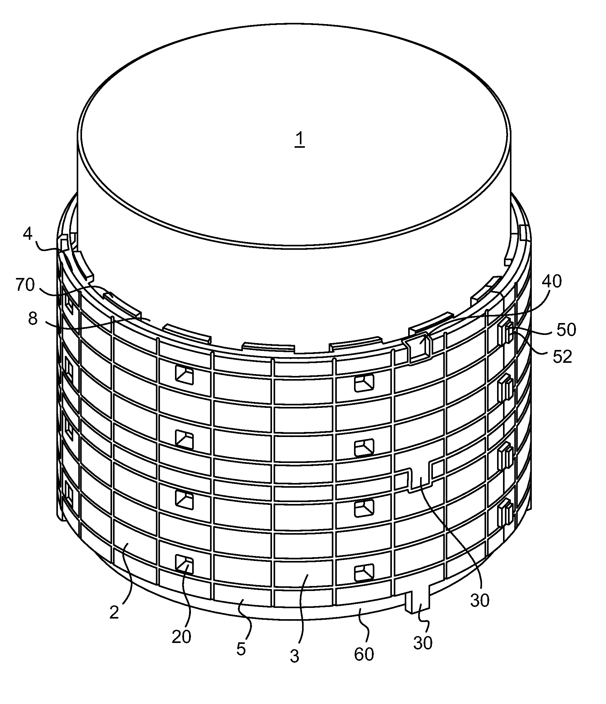
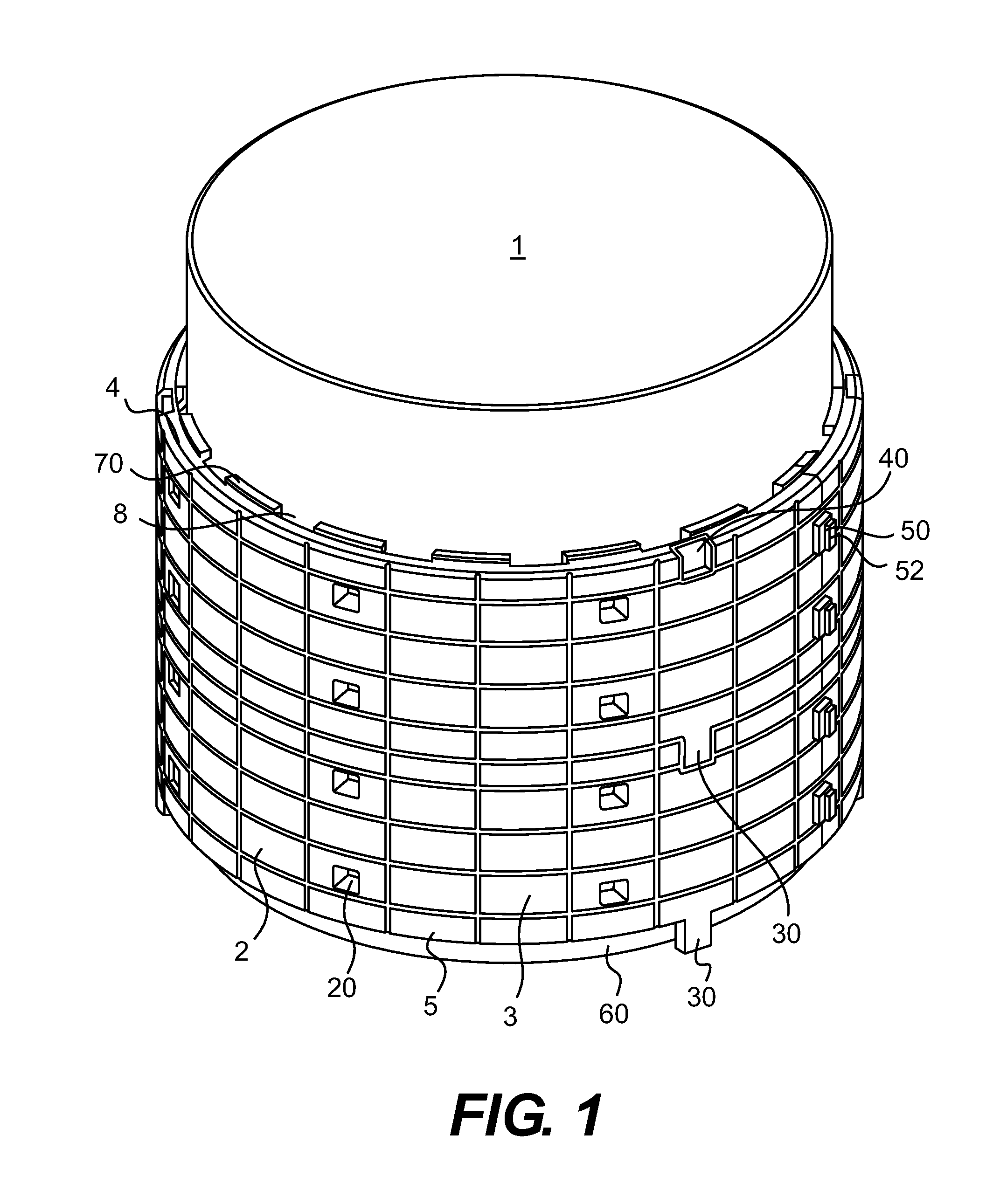
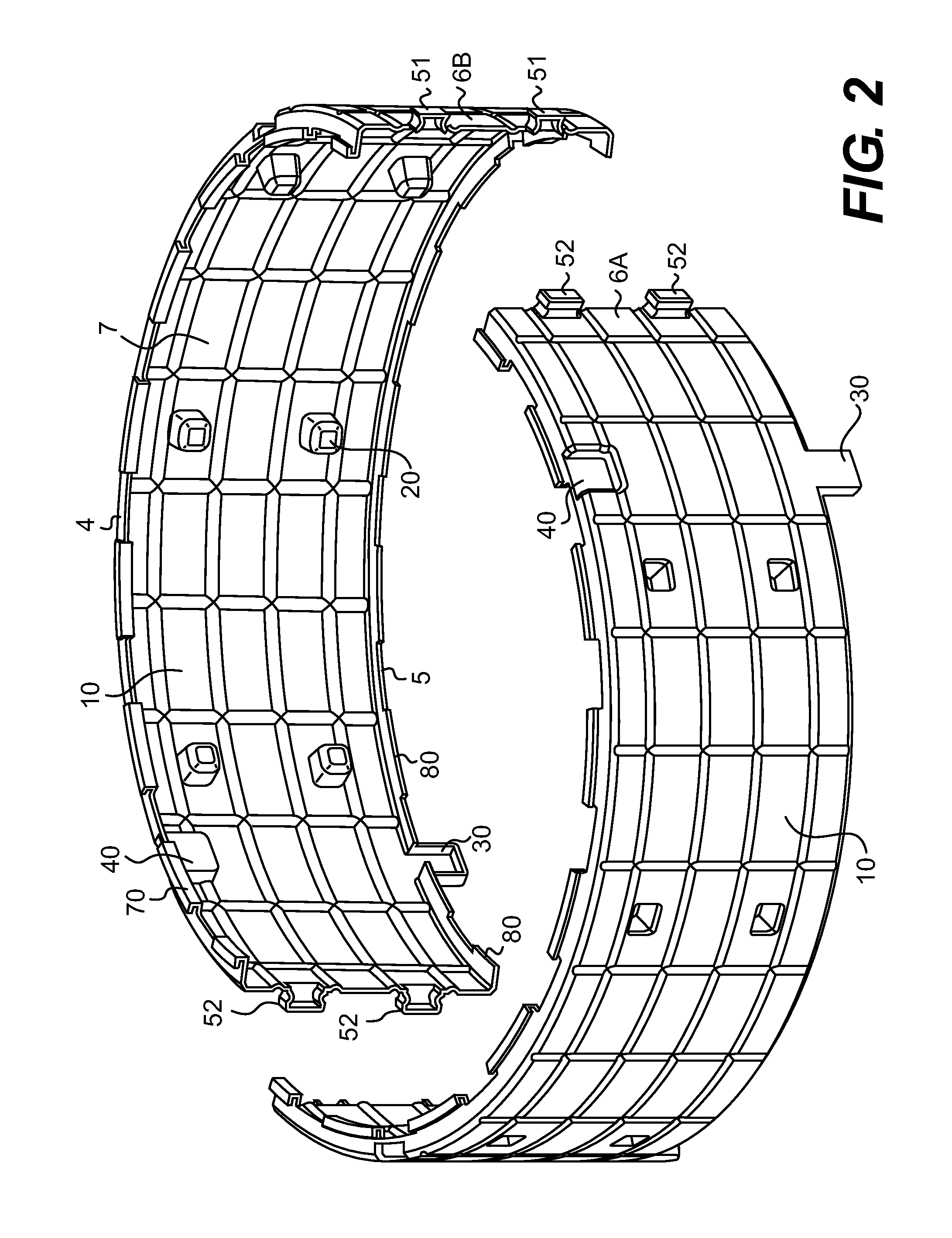
[0077]FIG. 4 shows a different view of the cover 2 shown in FIG. 3 and FIG. 5 is a cross section of FIG. 4 across the 5-5 line. The cover segment 10 of the first embodiment includes a plurality of connector tabs 51 and a plurality of tab receivers 52, constituting lateral connectors 50, formed into the cover segment 10. The connector tabs 51 are formed on one side (6B in FIG. 2) of a cover segment 10 and tab receivers 52 are formed on the opposite side (6A in FIG. 2) of a cover segment 10. FIG. 2 shows two cover segments 10, which are not connected; while FIG. 1 shows the cover segments 10 connected to form a cover 2 of the present invention. Sliding the connector tabs 51 on one cover segment 10 into the tab receivers 52 of another cover segment 10 makes a lateral connection. As shown in FIG. 2, the tab receivers 52 of side 6A of the cover segment 10 are configured to receive the connector tabs 51 of side 6B of another cover segment 10.

[0078]Upon connection, as shown in FIG. 1, the ...

second embodiment

[0082]The cover segment 10 of the present invention includes lateral connectors 50 of another configuration. FIGS. 13 and 15 show connector blocks 110, which are fastened using a sleeve 100. A plurality of connector blocks 110 are provided on the sides 6A, 6B of each cover segment 10. The connector blocks 110 are preferably formed in a block or cube type shape and extend outward from the outer surface 3 of the cover segment 10. As shown in FIGS. 13 and 15, a stop block 111 is provided on each connector block 110 to engage the sleeve 100. A C-shaped sleeve 100 is shown in FIGS. 14A and 14B which has 4 faces and is shaped to slide down the connector blocks 110 to maintain the connection of the cover segments 10. Sleeve notches 112 are formed to accept the open face of the sleeve 100.

[0083]The open ended face of the sleeve 100 faces the cover and slides down through sleeve notches 112 formed into each connector block 110. The sleeve notches 112 accept the opposing open ends of the slee...

third embodiment

[0084 includes yet another form of lateral connectors 50 of the present invention. Each cover segment 10 has a plurality of flange portions 120 for joining cover segments 10 in the lateral direction. As shown in FIGS. 16 and 18, the flange portions 120 extend outward from the outer surface 3 of cover segment 10 and are provided on the sides 6A, 6B of each cover segment 10. Upon connection of the cover segments 10 in the lateral direction to form a cover 2, the flange portions 120 of respective cover segments 10 become aligned and abut each other so that the respective faces of the flange portions 120 contact each other. The faces of the flange part 123 are substantially flat and are formed substantially perpendicular to the outer surface 3 of the cover 10. Further, upon abutment the faces of the flange part 123 appear even and flush to an observer.

[0085]As shown in FIG. 18, a shoulder portion 121 and a tie notch are formed into each flange portion 120. Flange portions 120 are provid...


PUM


Abstract

A cover is provided in modular form for covering support structures, including columns supporting overpasses on roadways. The cover is formed of cover segments that are connected together laterally and vertically. The cover segments are provided with multiple techniques for vertical and horizontal connection, air channels, stand offs, worker viewing areas, and drainage spaces. The cover is made of a lightweight material and allows for tolerance for expansion of the support structure material.

Description

[0001]This application claims the benefit of U.S. Provisional Application No. 61 / 747,635 filed Dec. 31, 2012, and U.S. Provisional Application No. 61 / 913,618 filed Dec. 9, 2013.FIELD OF THE INVENTION[0002]The invention relates to a modular cover for support structures having multiple cover segments connected together using multiple connection techniques.BACKGROUND OF THE INVENTION[0003]Covers for support structures, such as columns, include sleeves, shields, and wraps that cover the support structure. The covers are for protecting a support structure of, for example, a bridge or an overpass commonly located along roadways.[0004]In areas where snow and ice accumulate, and the snow is removed from the road by a snow plow or other snow removal device, road salts, chemicals, and other materials incidentally adhere to the support columns along the road. In many instances, the support structures are made of concrete. As a result, erosion and deterioration of the supports occurs necessitat...

Claims


Application Information

Patent Timeline
IPC IPC(8): E04F13/073
CPCE04F13/185E04F13/0736E04F13/0733E04C3/30E04H12/2292
Inventor HABODASZ, ANTHONY P.
Owner POLY SALT ARMOR LLC
Why Eureka
Try Eureka