Plasma reactor for carrying out gas reactions and method for the plasma-supported reaction of gases

a plasma-supported reaction and reactor technology, applied in the field of plasma-supported reaction reactors, can solve the problems of plasma breaking down, inability to achieve high gas flow velocities, and inability to permit throughput of larger volume flows and corresponding gas velocities, etc., to achieve stable long-term operation, high throughput, and optimal gas activation

Inactive Publication Date: 2014-07-03
IPLAS
View PDF1 Cites 11 Cited by
  • Summary
  • Abstract
  • Description
  • Claims
  • Application Information

AI Technical Summary

Benefits of technology

[0017]According to the invention, it is provided to form at least one, particularly central, zone in the gas stream which is flow-reduced by means of the flow-forming elements. Within such a flow-reduced zone, it is possible to produce the plasma in a particularly stable manner.
[0063]Possible reactions with catalysts are the formation of long-chain hydrocarbons with and without insertion of oxygen, similar to the Fischer-Tropsch process, of aromatic molecules, the synthesis of ammonia, as well as the yield increase and prevention of soot formation in the production of synthesis gas. The process is thus suitable for the production of ammonia or hydrazine from mixtures of hydrogen and nitrogen, with and without the use of catalysts. p The purification of waste gases results in the complete purification, by oxidation, of a variety of waste gases from unwanted, harmful or poisonous components such as carbon monoxide, dioxin, furans, fluorochlorinated hydrocarbons, fluorohydrocarbons, chlorohydrocarbons and further carbon compounds. The device enables the supply of, for example, air or oxygen, or of reductive gases such as ammonia, hydrogen or mixtures thereof with waste gases through the gas feeds. By selecting suitable temperatures, choosing suitable additives and effective catalysts, it is thus possible to also purify waste gases that are difficult to convert or the conversion of which is frequently incomplete.

Problems solved by technology

Arrangements according to DE 19600223, for example, indeed produce non-equilibrium or non-thermal plasmas, in plasma chambers having a volume of several times 1000 cm3 and power densities of several W / cm3, at a microwave excitation frequency of 2.45 GHz, but they do not permit throughput of larger volume flows and corresponding gas velocities.
With the known reactors, it is of disadvantage that a gas flow disturbs the plasma even at low flow rates and pushes the plasma out of the chamber and causes the plasma to break down, which is thereby extinguished.
It is not possible to achieve high gas throughputs and high gas flow velocities with the known reactors.
Known gas reactions and gas syntheses can also take place in the arc with discharge electrodes: here, the temperatures are too high for many purposes, the gas flow is impeded by the electrodes, and the high energy consumption is disadvantageous.

Method used


Image

  • Plasma reactor for carrying out gas reactions and method for the plasma-supported reaction of gases
  • Plasma reactor for carrying out gas reactions and method for the plasma-supported reaction of gases
  • Plasma reactor for carrying out gas reactions and method for the plasma-supported reaction of gases

Examples


Embodiment Construction

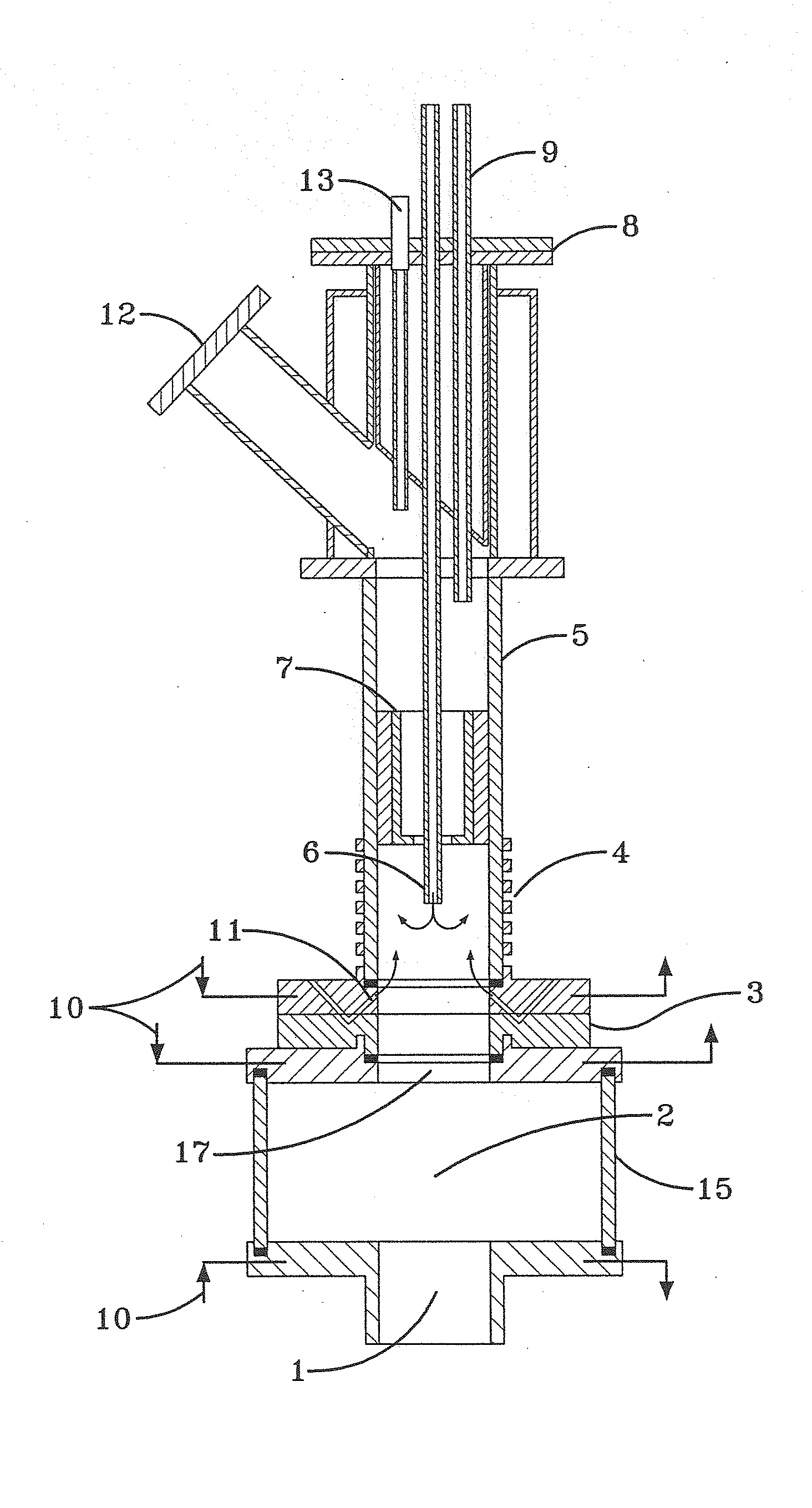
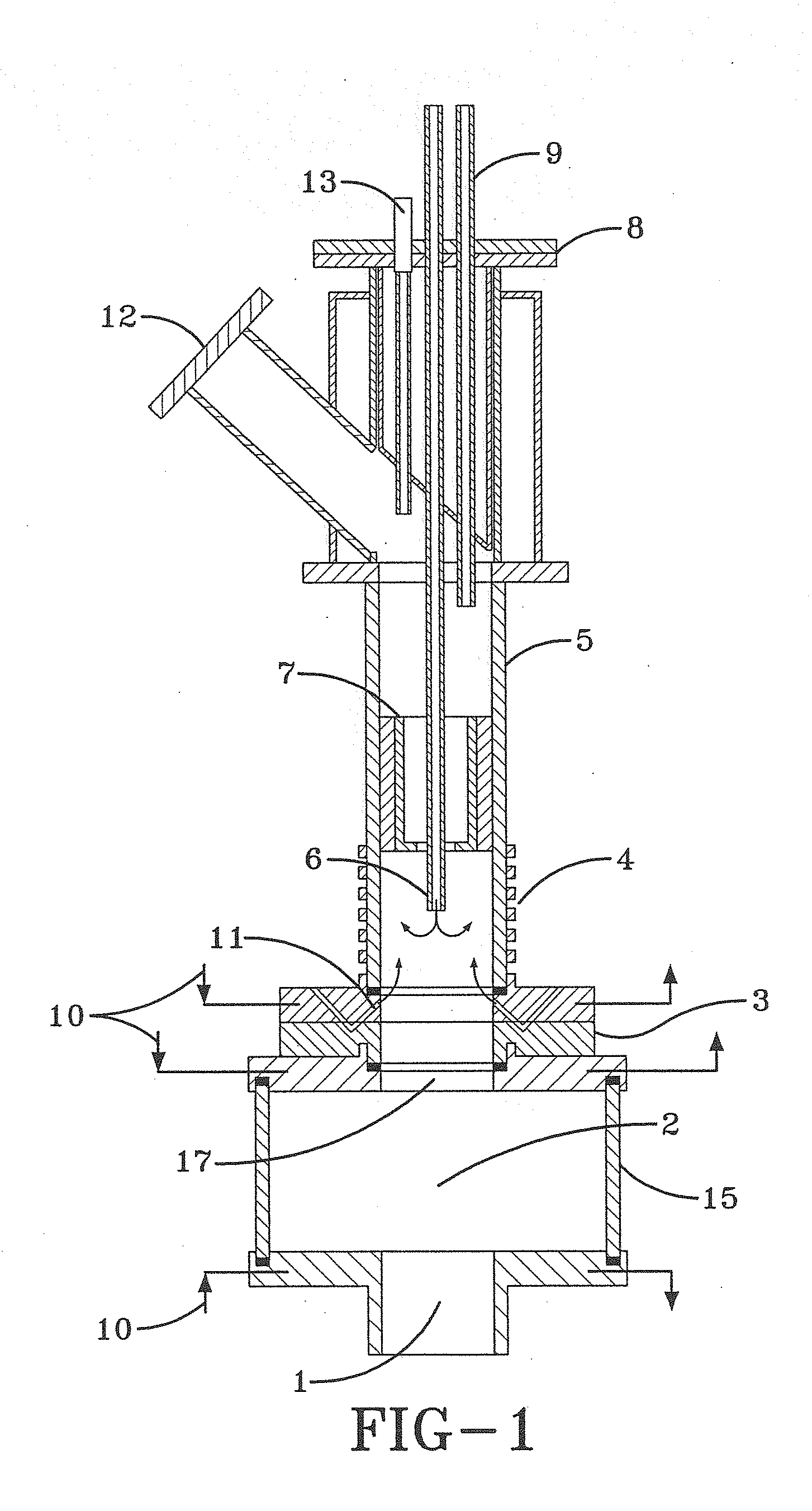
[0066]FIG. 1 shows a device, wherein a, for example, rotating, gas stream of the starting materials is introduced from below, through the end face of the plasma chamber, by means of the gas inlet 1, which is configured as a flow-forming element. The gas stream is distributed in the plasma reactor or in the plasma chamber 2, is guided further through the reaction tube 5, which has the same axis as the reactor, brought to full reaction, and is finally disposed at the gas outlet 12.

[0067]Cooling chambers 10, which are configured to be ring-shaped, and cooled rings 3 are arranged at the gas inlet into the reactor and at the gas outlet of the reactor, respectively the inlet into the reaction tube. Feed lines for further gases or auxiliary substances are arranged in the form of annular nozzles 11 at the outlet of the reactor, and as displaceable axial tube 6 with gas introduction towards the gas stream. A measuring device 13 and a displaceable sampling device 9 are inserted through the co...


PUM

PropertyMeasurementUnit
pulse frequenciesaaaaaaaaaa
volumeaaaaaaaaaa
frequencyaaaaaaaaaa

Abstract

A device for carrying out gas reactions, comprising a plasma reactor with a through-flow of gases which has a, particularly cylindrical, plasma chamber, wherein flow-forming elements for forming a flow of gases are arranged before and / or in and / or after the plasma reactor in order to form a gas stream within the plasma chamber such that at least one, particularly central, zone in the gas flow is formed which is flow-reduced. A method for carrying out gas reactions is also provided.

Description

CROSS-REFERENCE TO RELATED APPLICATIONS[0001]This application is a divisional application of co-pending application Ser. No. 10 / 521,874, filed on Jul. 25, 2005, which is a 35 U.S.C. 371 national stage filing of International Application No. PCT / EP2003 / 007993 filed on Jul. 22, 2003, which claims priority of German application number 102 33 538.9, filed on Jul. 23, 2002. The contents and disclosures of all the aforementioned applications are incorporated herein by reference in their entireties.BACKGROUND OF THE INVENTION[0002]1. Field of the Invention[0003]The invention relates to a device for carrying out gas reactions, the device comprising a plasma reactor with a through-flow of gases, particularly a large-volume plasma reactor, which has a plasma chamber, particularly a cylindrical plasma chamber. The invention further relates to a method for carrying out gas reactions wherein a flow of gases or a flow of gasifiable substances is guided through a plasma, especially a plasma that i...

Claims


Application Information

Patent Timeline
Patent Type & Authority Applications(United States)
IPC IPC(8): B01J19/12B01D53/32C01B3/38C01B21/16C01C1/04H01J37/00H01J37/32H05B6/78H05B6/80
CPCB01J19/126B01D53/32B01J2219/0254B01J2219/0286B01J2219/0869B01J2219/0871B01J2219/0883B01J2219/0892B01J2219/0894B01J2219/1227C01B3/384C01B21/16C01B2203/0233C01B2203/0238C01B2203/1023C01B2203/1041C01B2203/1047C01B2203/1064C01B2203/107C01B2203/1076C01B2203/1082C01B2203/1241C01C1/0417H01J37/3244H05B6/78H05B6/80H05B6/806Y02P20/52Y02P20/141H01J37/00H01J37/32
Inventor SPITZL, RALFBEHR, ARNOWOLFF, CHRISTIANOBERREUTHER, THORSTEN
Owner IPLAS
Why Eureka
Try Eureka