
Non-contact magnetostrictive sensing systems and methods

a non-contact, magnetic sensing technology, applied in the direction of instruments, magnetic property measurements, force measurements, etc., can solve the problems of high cost of operation, difficult to retrofit existing systems with a magnetostrictive sensing system, and difficult to accurately measur

Active Publication Date: 2014-07-03
BAKER HUGHES INC
View PDF4 Cites 41 Cited by
  • Summary
  • Abstract
  • Description
  • Claims
  • Application Information

AI Technical Summary

Benefits of technology

The patent describes a system and method for measuring stress and torque in ferromagnetic materials using a magnetic flux device and a sensor. The sensor detects changes in the magnetic flux caused by the stress and torque, and transmits signals that indicate these changes. This technology can provide a non-destructive and accurate way to measure these properties of ferromagnetic materials.

Problems solved by technology

The changes in the magnetic permeability due to stress applied to the ferromagnetic material, however, may be small, making accurate measurement difficult.
Such an operation is typically expensive.
In addition, such an operation makes it more difficult to retrofit existing systems with a magnetostrictive sensing system because the material to be sensed may have to be removed from the system to undergo permanent magnetic encoding, e.g., a shaft of a gas turbine engine.
In such a system, steady state stress measurements may not be accurately measured or may be necessarily difficult to acquire.

Method used


Image

  • Non-contact magnetostrictive sensing systems and methods
  • Non-contact magnetostrictive sensing systems and methods
  • Non-contact magnetostrictive sensing systems and methods

Examples


Embodiment Construction

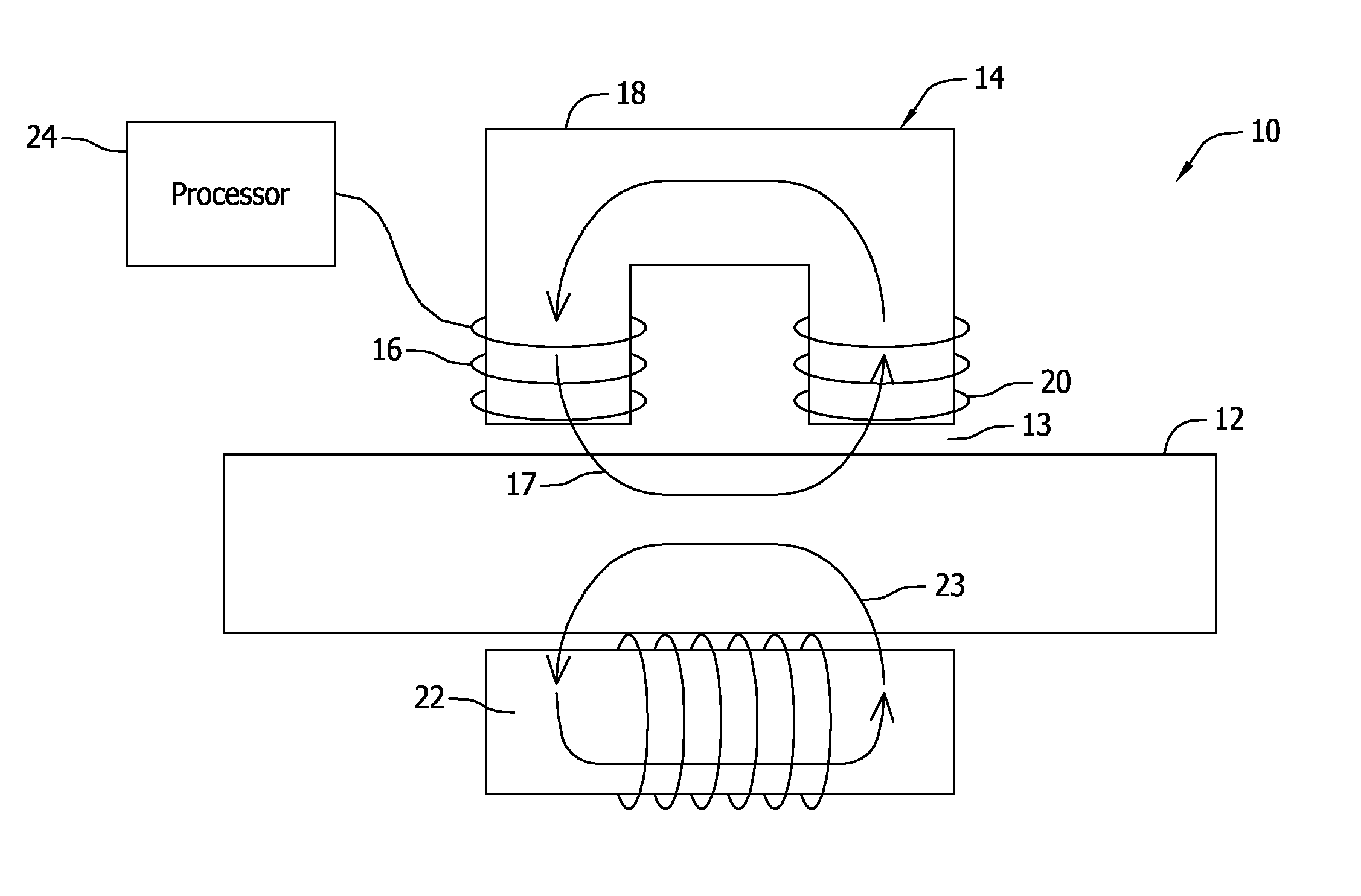
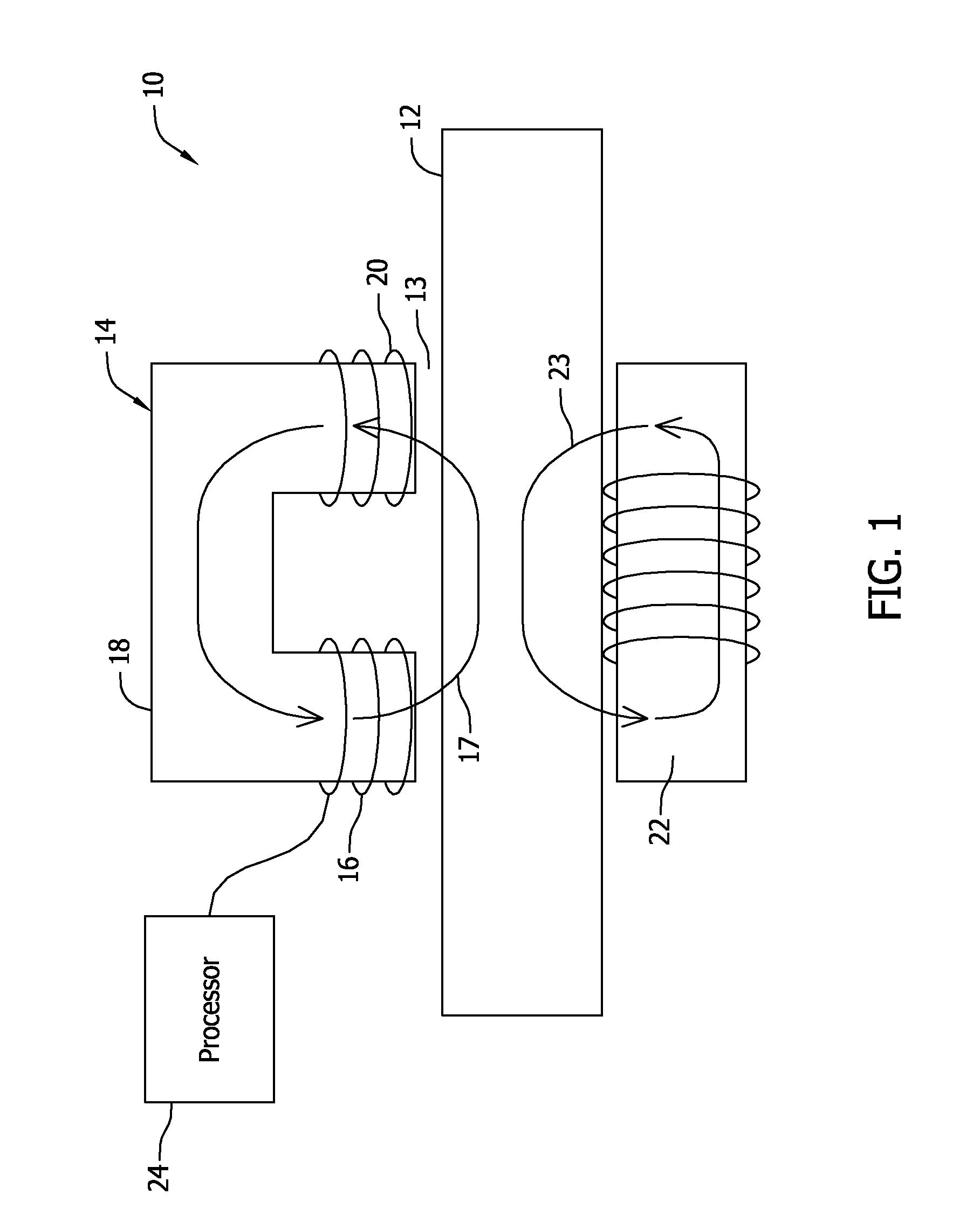
[0013]FIG. 1 is a schematic view of a stress sensing system 10 for sensing the stress in a ferromagnetic material 12. Stress sensing system 10 includes a magnetic flux device 22 for inducing a first conditioning magnetic flux 23 in ferromagnetic material 12. Conditioning magnetic flux 23 induced in ferromagnetic material 12 facilitates increasing the signal-to-noise ratio (SNR) of the magnetic signal to be detected and signal linearity, and reduces the hysteresis associated with stress sensing system 10. By increasing the SNR, magnetic flux device 22 facilitates measuring stresses in ferromagnetic material 12 with less total current being required to operate stress sensing system 10. The lower current requirement permits stress sensing system 10 to be operated in hazardous environments where prior magnetostrictive sensors could not be used.

[0014]As used herein, the term “hysteresis” refers to the irreversibility in magnetic permeability of a ferromagnetic material with respect to th...


PUM

PropertyMeasurementUnit
sensing stressaaaaaaaaaa
magnetic fluxaaaaaaaaaa
stressaaaaaaaaaa

Abstract

A system for sensing stress in a ferromagnetic material is provided. The system includes at least one magnetic flux device configured to induce a conditioning magnetic flux in the ferromagnetic material. The system also includes a sensor positioned proximate to the ferromagnetic material. The sensor includes a core, at least one excitation coil configured to induce a second magnetic flux in the ferromagnetic material, and at least one detector configured to detect changes in the second magnetic flux.

Description

BACKGROUND OF THE INVENTION[0001]The subject matter described herein relates generally to stress sensing in ferromagnetic materials, and more particularly, to non-contact systems and methods for the sensing of stress in ferromagnetic materials.[0002]Ferromagnetic materials have a magnetostrictive property that causes the materials to change shape in the presence of an applied magnetic field. The inverse is also true. When a force is applied to a ferromagnetic material, the magnetic properties, such as magnetic permeability, of the material change. A magnetostrictive sensor may sense the changes in magnetic permeability and, because the changes are proportional to the amount of stress applied to the ferromagnetic material, the resulting measurement may be used to calculate the amount of stress.[0003]The changes in the magnetic permeability due to stress applied to the ferromagnetic material, however, may be small, making accurate measurement difficult. At least some known magnetostri...

Claims


Application Information

Patent Timeline
Patent Type & Authority Applications(United States)
IPC IPC(8): G01L1/12
CPCG01L1/125G01L1/122G01L1/127G01L3/102G01L3/105
Inventor CAMPBELL, LAM ARTHURSIPILA, PEKKA TAPANI
Owner BAKER HUGHES INC
Learn More