
Apparatus and method for identifying a hook effect and expanding the dynamic range in point of care immunoassays

a technology of immunoassay and antibody, applied in the field of analytical testing devices, can solve the problems of insufficient amount of signal antibody remaining to bind to analyte, increased analysis cost, delay,

Active Publication Date: 2014-07-03
ABBOTT POINT CARE
View PDF4 Cites 15 Cited by
  • Summary
  • Abstract
  • Description
  • Claims
  • Application Information

AI Technical Summary

Benefits of technology

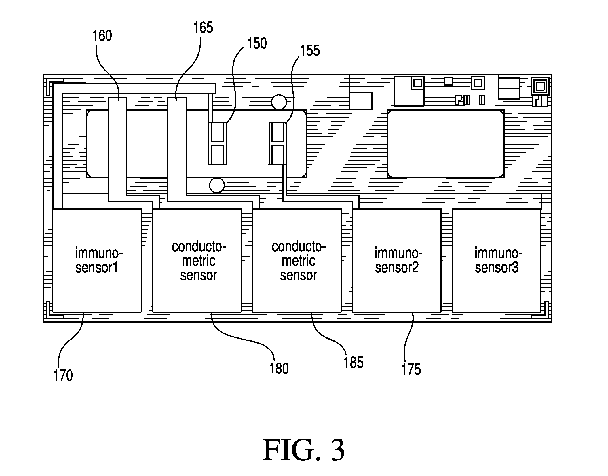
The present invention provides a dual immunosensor cartridge that can detect a certain substance in a biological sample. To operate the cartridge, a portion of the sample is placed in the sample chamber, then into a reading apparatus. An antibody-enzyme conjugate is added to the sample, and it is then contacted with the two immunosensors. A second fluid containing an electro-inactive substrate for the enzyme is used to rinse the immunosensors. The electrical response of the two immunosensors is recorded and analyzed for the presence or amount of the substance of interest and / or the presence of a hook effect.

Problems solved by technology

Laboratory testing increases the cost of analysis and delays the results.
In many circumstances, delay can be detrimental to a patient's condition or prognosis, such as for example the analysis of markers indicating myocardial infarction.
In particular, the high concentration of target analyte may result in substantially all of the signal antibody within the immunoassay binding to free analyte in the sample, and thus an insufficient amount of signal antibody remains to bind to analyte that is bound to the capture antibodies of the immunoassay.

Method used


Image

  • Apparatus and method for identifying a hook effect and expanding the dynamic range in point of care immunoassays
  • Apparatus and method for identifying a hook effect and expanding the dynamic range in point of care immunoassays
  • Apparatus and method for identifying a hook effect and expanding the dynamic range in point of care immunoassays

Examples


examples

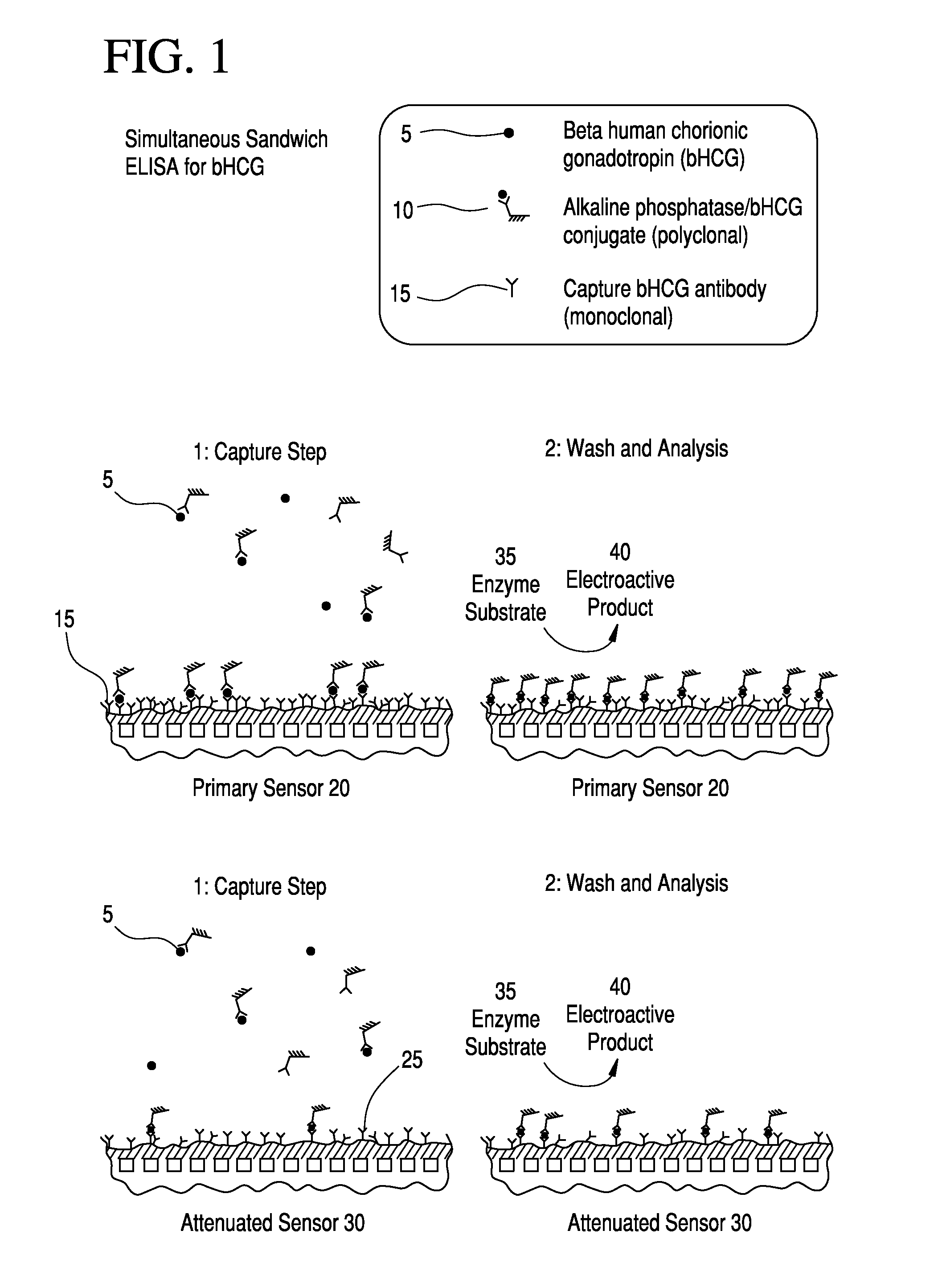
[0124]For purposes of illustration and not limitation, the following examples provide information on the hook effect and some aspects of the present invention including the attenuated sensor configured to detect the presence of the hook effect.

[0125]Dose-response results (e.g., raw immunosensor currents) obtained using human chorionic gonadotropin (hCG) and an hCG-responsive amperometric immunosensor are shown in FIG. 14. Amounts of hCG equivalent to 0 to 200 miU / mL were allowed to bind to the immobilized antibody attached to the electrode, as in FIG. 4. As shown in FIG. 15, good sensitivity of the response of the attenuated sensor to increasing hCG was found. Consequently, it was demonstrated that preferred embodiments of the present invention may precisely and rapidly quantify hCG in a sample.

[0126]With regard to handling more subtle differences between the pair of sensors, e.g., where there is a characteristic constant offset between the pair of sensors, the offset can be subtrac...


PUM

PropertyMeasurementUnit
thicknessaaaaaaaaaa
diameteraaaaaaaaaa
diameteraaaaaaaaaa

Abstract

The present invention relates to systems and methods for the rapid in situ determination of the existence of a hook effect and expansion of the dynamic range of a point of care immunoassay. For example, a system for identifying a hook effect and expanding the dynamic range of an immunoassay is provided that may include a primary sensor having first immobilized antibodies that may be configured to generate a first signal based on a presence or absence of a target analyte in a sample. The system may further include an attenuated sensor having second immobilized antibodies at a reduced concentration relative to a concentration of the first immobilized antibodies on the primary sensor and that may be configured to generate a second signal based on the presence or absence of the target analyte in the sample. The system may further include a processor configured to determine a presence of a hook effect in the immunoassay based on relative values of the first and second signals and optionally determine the target analyte concentration of the sample.

Description

CROSS-REFERENCE TO RELATED APPLICATIONS[0001]This is a non-provisional of Provisional Appl. 61 / 746,705, filed Dec. 28, 2012, the entirety of which is incorporated herein by reference.FIELD OF THE INVENTION[0002]The invention relates to analytical testing devices and methods of using same. Specifically, the invention relates to systems and methods for the rapid in situ determination of the existence of a hook effect and expanding the dynamic range in immunoassays, and in particular in point of care immunoassays.BACKGROUND OF THE INVENTION[0003]A multitude of laboratory tests for analytes of interest are performed on biological samples for diagnosis, screening, disease staging, forensic analysis, pregnancy testing, drug testing, and other reasons. While a few qualitative tests, such as pregnancy tests, have been reduced to simple kits for the patient's home use, the majority of quantitative tests still require the expertise of trained technicians in a laboratory setting using sophisti...

Claims


Application Information

Patent Timeline
Patent Type & Authority Applications(United States)
IPC IPC(8): G01N33/543
CPCG01N33/54366G01N33/5306G01N33/5438G01N33/54393
Inventor CAMPBELL, JOHNNGUYEN, LINDASMITH, JAMESWEISS, WENDADOWELL, BARRY LEE
Owner ABBOTT POINT CARE
Learn More