EGR Rate Control For Internal Combustion Engine With Dual Exhaust-Ported Cylinders

Active Publication Date: 2014-07-10
SOUTHWEST RES INST
View PDF15 Cites 34 Cited by
  • Summary
  • Abstract
  • Description
  • Claims
  • Application Information

AI Technical Summary

Problems solved by technology

The dilution of the oxygen present in the com

Method used


Image

  • EGR Rate Control For Internal Combustion Engine With Dual Exhaust-Ported Cylinders
  • EGR Rate Control For Internal Combustion Engine With Dual Exhaust-Ported Cylinders
  • EGR Rate Control For Internal Combustion Engine With Dual Exhaust-Ported Cylinders

Examples


Embodiment Construction

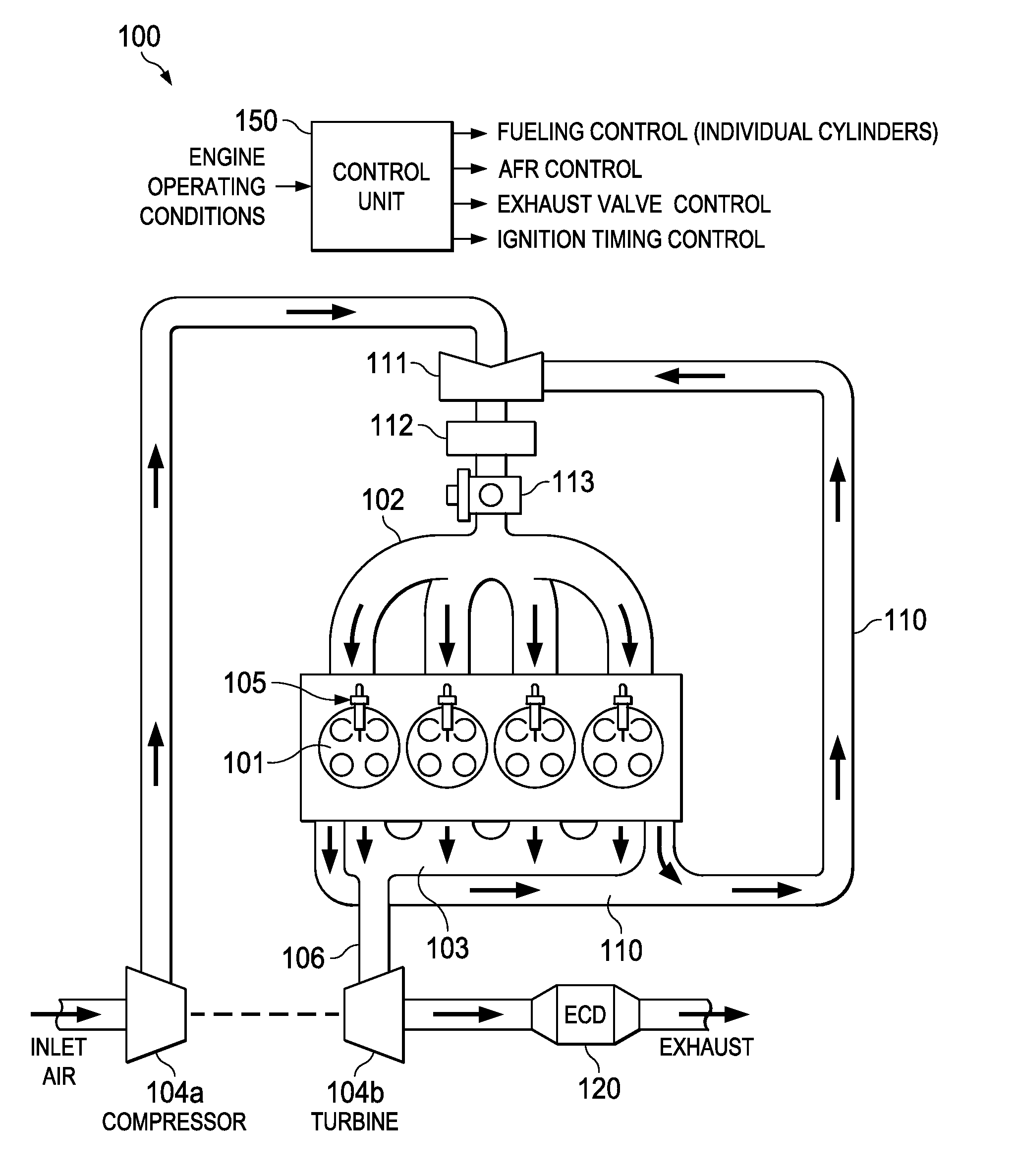
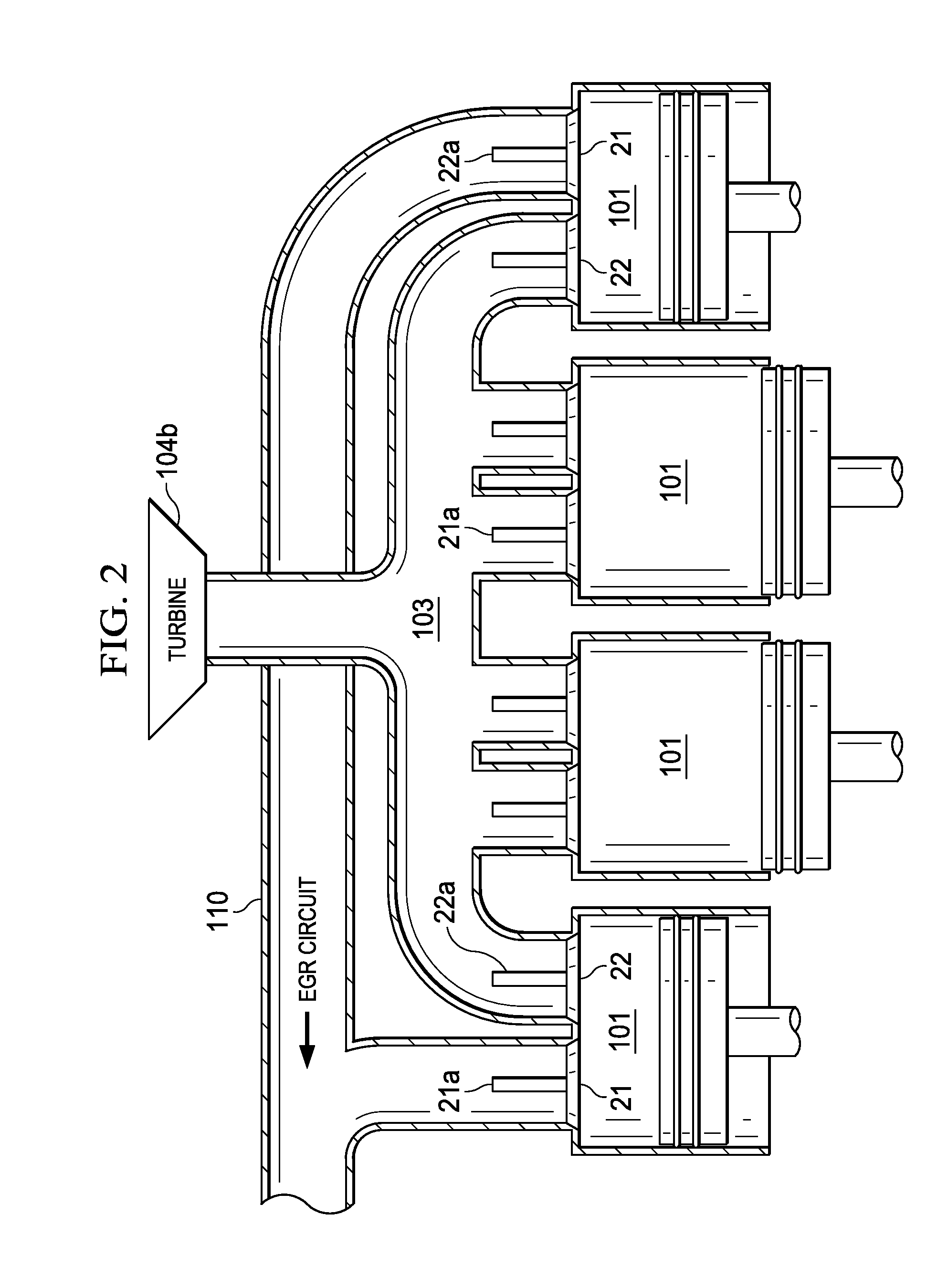
[0010]As described in the Background, EGR has significant advantages for internal combustion engines. The embodiments described below add control over EGR composition as another important variable to the engine control strategy. In conventional engines, EGR composition is equivalent to the engine-out exhaust composition. The EGR system and control method herein disconnect the EGR gas from the tail-pipe exhaust. By doing so, EGR composition can be controlled to positively impact engine performance and efficiency.

[0011]A recent development in the area of exhaust gas recirculation (EGR) for internal combustion engines is the use of one or more of the engine's cylinders as a “dedicated EGR” cylinder. The exhaust of the dedicated EGR cylinder(s) is routed back to the intake of all the cylinders, thereby creating EGR for all cylinders with the exhaust of a few. The dedicated EGR cylinder(s) can operate at any equivalence ratio since its exhaust will never exit the engine before passing th...


PUM


Abstract

A method of using exhaust gas recirculation (EGR) in an internal combustion engine. At least two of the cylinders are “dual exhaust-ported cylinders” having two exhaust ports. For each of these cylinders, one of the exhaust ports is connected to the EGR loop and the other of the exhaust ports is connected to the main exhaust line. These cylinders are controlled such that one exhaust port is open and the other exhaust port is closed during each engine cycle, and are operated, on a cycle-by-cycle basis so that all of the exhaust produced by a cylinder may be delivered to the EGR loop at any cycle. The number of cylinders operating as EGR cylinders per engine cycle is in response to a desired EGR rate.

Description

TECHNICAL FIELD OF THE INVENTION[0001]This invention relates to internal combustion engines, and more particularly to an improved exhaust gas recirculation system for such engines.BACKGROUND OF THE INVENTION[0002]For many internal combustion engines, their engine control strategy has three important parameters: spark timing (or fuel injection timing in a diesel engine), the exhaust gas recirculation (EGR) rate and the air / fuel ratio (AFR).[0003]To implement EGR, a fraction of the exhaust gas is recycled from the exhaust system back to the intake system. The recirculated exhaust gas is mixed with the fresh fuel-air mixture before entering the cylinders. EGR can be implemented in internal and external configurations. External configurations can be implemented as either a high pressure or low pressure loop, depending on whether the recirculated exhaust is introduced to the intake post compressor (high pressure loop) or pre-compressor (low pressure loop).[0004]EGR has a long history of ...

Claims


Application Information

Patent Timeline
IPC IPC(8): F02M25/07F02B47/08
CPCF02B47/08F02M25/077F01N13/107F02D13/0246F02D13/0257F02D41/005F02D41/0065F02D41/008F02M26/05F02M26/43Y02T10/12Y02T10/40
Inventor GINGRICH, JESS W.GUKELBERGER, RAPHAEL
Owner SOUTHWEST RES INST
Why Eureka
Try Eureka