Virtual parallel load bank system

a load bank and virtual technology, applied in the direction of power supply testing, ac-dc network circuit arrangement, ac network voltage adjustment, etc., can solve the problems of inability to provide a specific high level of current to a voltage source, lack of versatility

Inactive Publication Date: 2014-07-10
EXPERIUM TECH
View PDF9 Cites 6 Cited by
  • Summary
  • Abstract
  • Description
  • Claims
  • Application Information

AI Technical Summary

Benefits of technology

[0006]According to another embodiment of the invention, a method for creating a virtual load bank to supply a current to the terminals of a voltage source is provided. In accordance with the method, a load bank is connected in parallel with the source terminals. One of the loads of the load bank is designated as a master load for connection with the terminals. The master load sends an inquiry to other loads in the load bank via a communication network to determine the availability of the other loads for connection with the source terminals. From among the available loads, a least one other load is connected in parallel with the master load and the source terminals to precisely create and control the current supplied to the source terminals in accordance with the loads.

Problems solved by technology

While the prior devices operate satisfactorily, they lack versatility in that they are not capable of providing a specific high level of current to a voltage source, such as is necessary for testing the source.

Method used


Image

  • Virtual parallel load bank system
  • Virtual parallel load bank system
  • Virtual parallel load bank system

Examples


Embodiment Construction

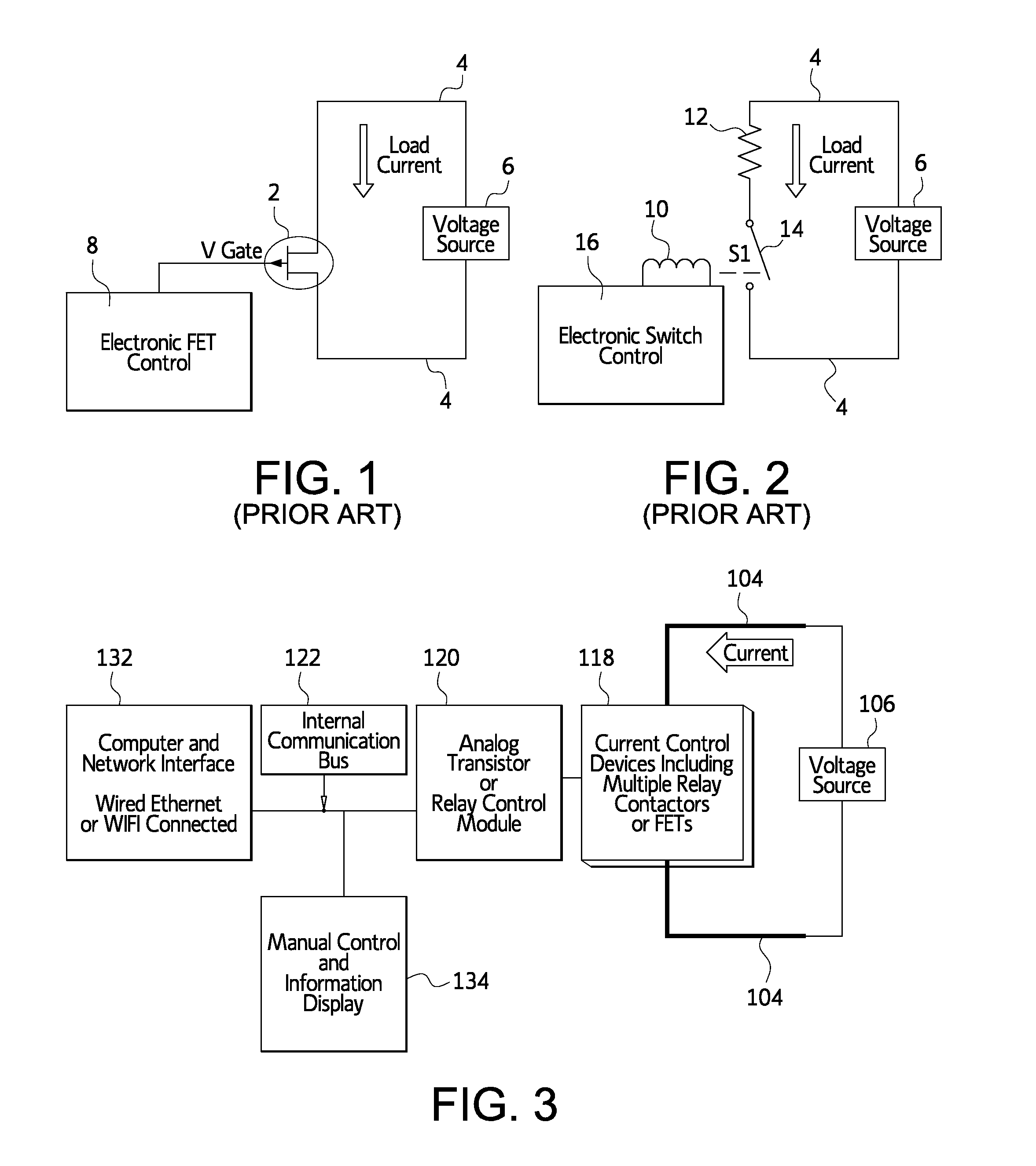
[0019]FIGS. 1 and 2 show load systems according to the prior art. In FIG. 1 there is shown a field effect transistor (FET) 2 connected across the terminals 4 of a voltage source 6. The transistor is an electric device where the current through the device is controlled by the voltage applied to a specific terminal. In FIG. 1, the load current through two terminals of the transistor 2 is proportional to the voltage applied to the gate terminal. This voltage is the gate voltage Vgate which is provided from an electronic control device 8 for the field effect transistor.

[0020]In FIG. 2, a fixed inductor 10 or a fixed resistor 12 is connected across the terminals 4 of the voltage source 6. A relay 14 is connected in series with the inductor and resistor. It is readily understood by those of ordinary skill in the art that a capacitive device may be used as well. An electronic switch controller 16 operates the relay to determine whether the inductor or resistor or both are connected with th...


PUM


Abstract

A virtual parallel load bank system is characterized by a load band connected in parallel with the source terminals of a voltage source to create a specific current to be applied to the terminals. The load bank includes a plurality of loads that are selectively connected in accordance with the desired current for the voltage source. One load device is designated as a master load and a communication network is connected with the load devices to enable the master load device to communicate with the other load devices to determine which are available for connection in the virtual load bank system.

Description

BACKGROUND OF THE INVENTION[0001]A load bank is an electronically activated system that creates an electrical current load on a voltage source by using the current control capacity of a field effect transistor or fixed resistive, capacitive or inductive elements switched across the voltage source. The present invention relates to a virtual parallel load bank system in which a plurality of loads can be automatically or selectively connected across a voltage source to control the current supplied to the source.BRIEF DESCRIPTION OF THE PRIOR ART[0002]Load banks are well known in the patented prior art as evidenced by the Fong U.S. Pat. No. 7,683,553 which discloses a current control circuit in which matching drive currents through a plurality of parallel loads are set. A regulated voltage is provided to one terminal of a capacitor and to one terminal of each load and provides a source of current for the loads. The Tanner U.S. Pat. No. 7,479,713 discloses a fixed output linear voltage r...

Claims


Application Information

Patent Timeline
Patent Type & Authority Applications(United States)
IPC IPC(8): H02J4/00
CPCH02J4/00G01R31/40
Inventor PALATINI, LANCE
Owner EXPERIUM TECH
Why Eureka
Try Eureka