
Low profile omni-directional planar antenna with WIFI video streaming capability through broadband network

a broadband network and low-profile technology, applied in the direction of antennas, antenna details, electrical equipment, etc., can solve the problems of poor reception, attenuation of wifi signals, and inability to receive local tv news and programs normally provided by cable tv service, so as to improve the reception of wifi signals of video streaming devices

Active Publication Date: 2014-07-10
VOXX INT CORP
View PDF1 Cites 16 Cited by
  • Summary
  • Abstract
  • Description
  • Claims
  • Application Information

AI Technical Summary

Benefits of technology

The present invention is about combining two functions into a single device: video streaming through WIFI signal and receiving local TV programs through off-air signal. The invention provides a high definition television antenna on which a video streaming device can be mounted, improving WIFI signal reception and solving the need for separate power supplies. The modification allows for easy mounting and coupling with the video or audio streaming device without interfering with the reception elements or amplifier circuitry of the antenna. The technical effects are improved convenience and functionality for users.

Problems solved by technology

Many consumers subscribe to Netflix™, Hulu™ or Roku™ in order to avoid the expensive monthly service charge from the cable TV company, and by doing so they will not be able to receive those local TV news and programs that are normally provided by the cable TV service.
Companies such as Roku™, Google™ and other service companies that provide video on demand (VOD) or audio and video on demand (AVOD) services always face the same problem due to lack of capability to provide the local TV signals or programs with their audio and video streaming devices and services.
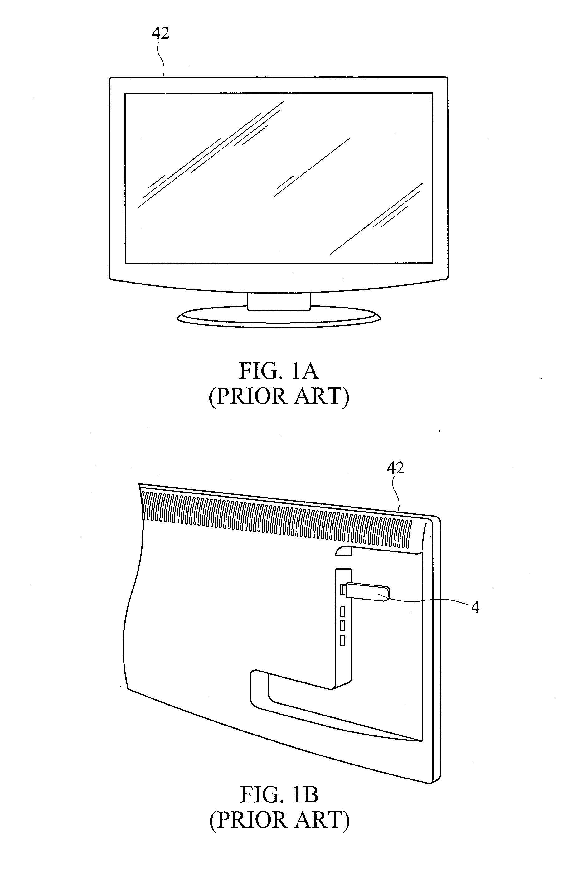
However, with the Roku Stick installed in this manner, WiFi signals may be attenuated by the television, and reception may be poor.

Method used


Image

  • Low profile omni-directional planar antenna with WIFI video streaming capability through broadband network
  • Low profile omni-directional planar antenna with WIFI video streaming capability through broadband network
  • Low profile omni-directional planar antenna with WIFI video streaming capability through broadband network

Examples


Embodiment Construction

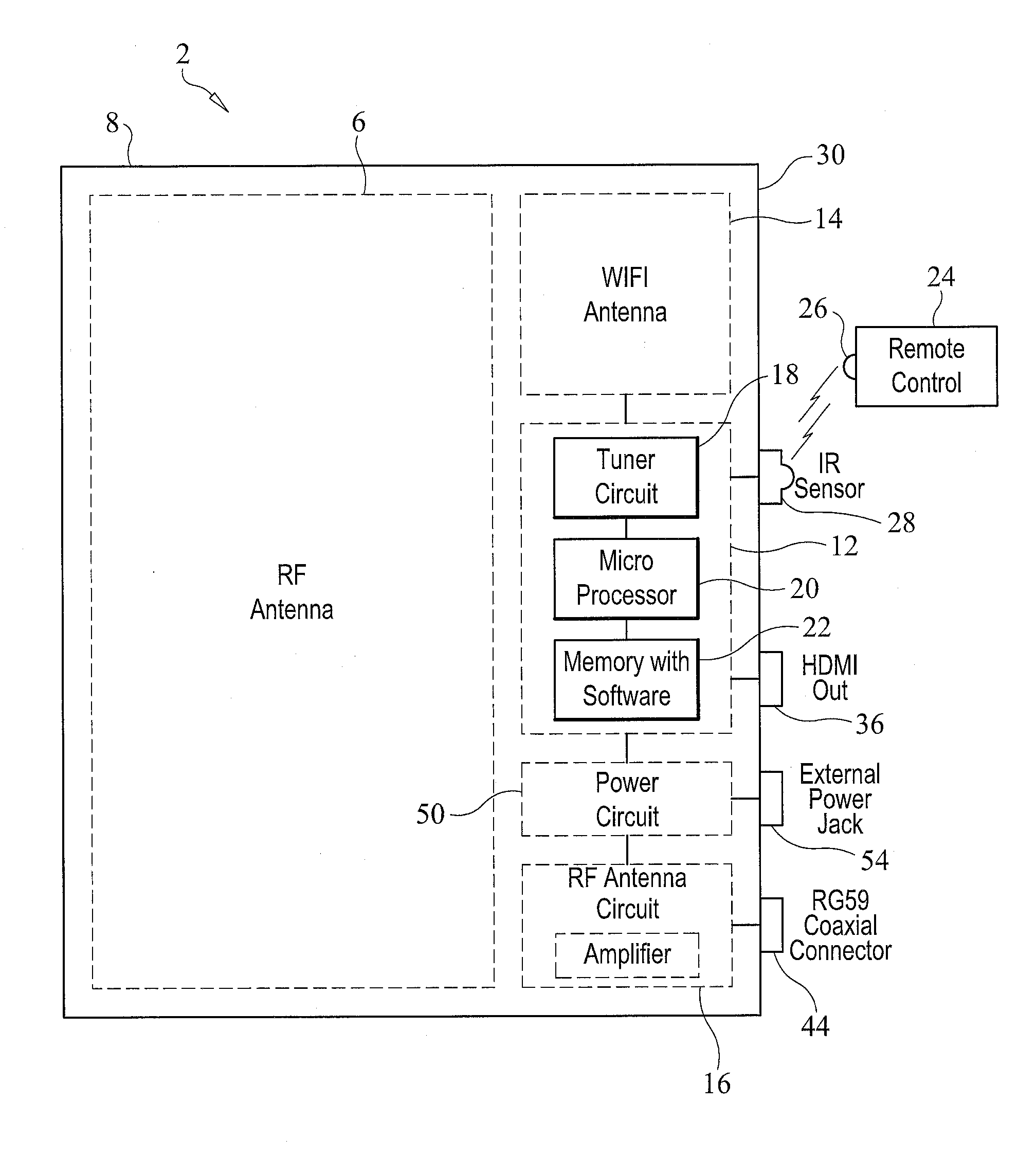
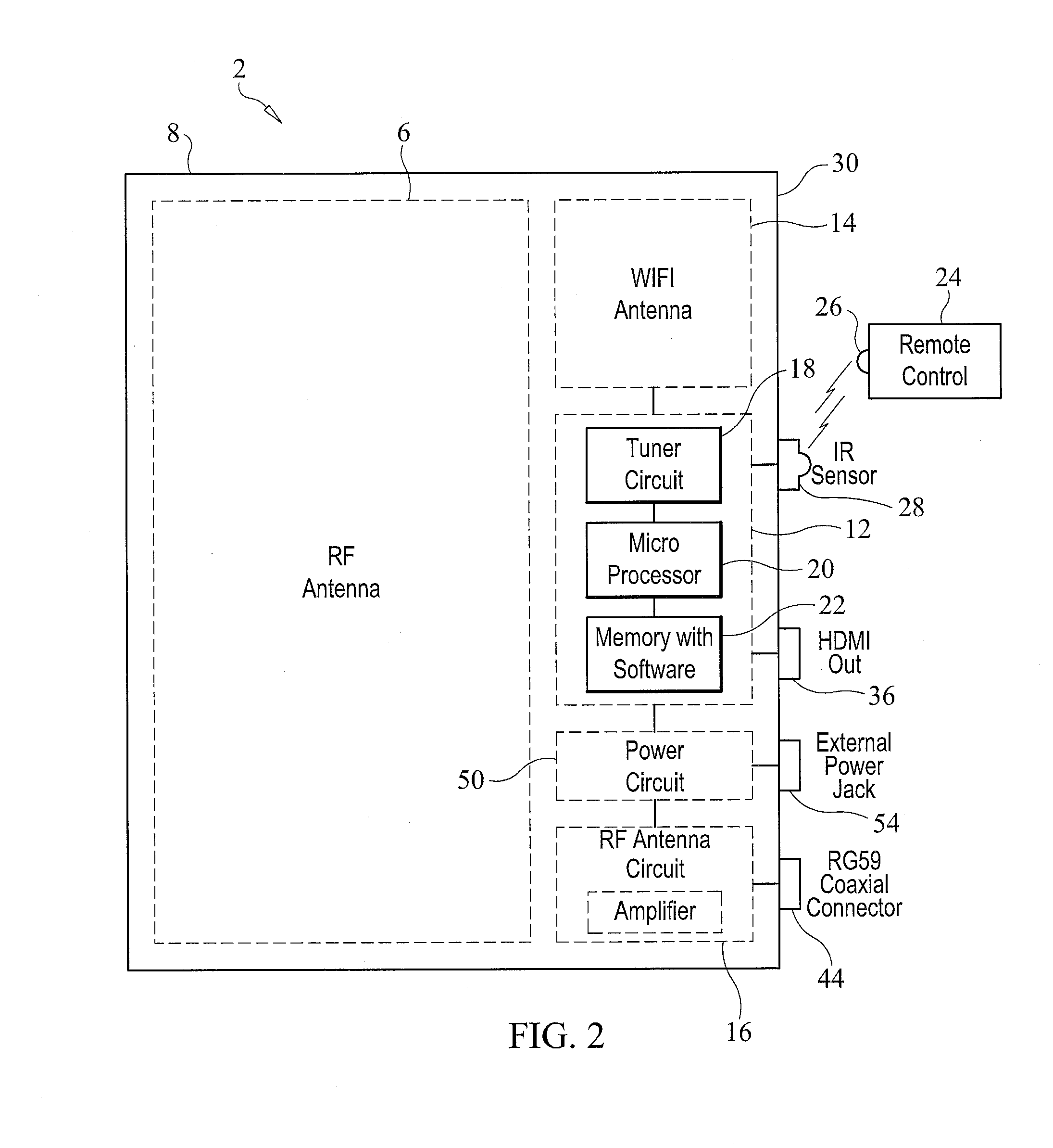
[0023]The antenna device 2 of the present invention combines a WiFi data or audio streaming device 4, such as the Roku Stick, with a low profile, high definition antenna 6, such as disclosed in U.S. Pat. No. 8,269,672, which issued on Sep. 18, 2012 to Prapan Paul Tinaphong, et al., and is entitled “Omni-Directional, Multi-Polarity, Low Profile Planar Antenna”, the disclosure of which is incorporated herein by reference. The term “WiFi” used herein means wireless fidelity or wireless access to the internet. Furthermore, the term “HDMI” used herein means “high definition multimedia interface”, and the term “USB” used herein means “universal serial bus”.

[0024]The antenna device 2 of the present invention has an antenna housing 8 which may include a port, with a USB, HDMI or MHL connector 10, which is capable of receiving an external, separate WiFi video or audio streaming device 4, such as a Roku Stick. Alternatively, the WiFi video or audio streaming circuit, including a high gain ant...


PUM


Abstract

An antenna device includes a housing defining an interior cavity, and an RF antenna situated within the housing. The RF antenna receives high definition television signals broadcast over the air. An MHL connector is mounted on the housing. An external audio or video streaming signal device is coupleable to the MHL connector. An MHL to HDMI converter circuit situated within the interior cavity of the housing receives signals from the external audio or video streaming signal device and processes these signals into an HDMI signal format. The HDMI signals are provided on an HDMI output connector mounted on the housing. RF signals from the RF antenna are provided to an RF coaxial cable connector also mounted on the housing.

Description

CROSS-REFERENCE TO RELATED APPLICATIONS[0001]This application is related to U.S. Provisional Patent Application Ser. No. 61 / 750,144, which was filed on Jan. 8, 2013, and is entitled “Low Profile Omni-Directional Planar Antenna With WiFi Video Streaming Capability Through Broadband Network”, the disclosure of which is hereby incorporated by reference and on which priority is hereby claimed.BACKGROUND OF THE INVENTION[0002]1. Field of the Invention[0003]The present invention relates to high definition television antennas, and video and audio data streaming devices.[0004]2. Description of the Prior Art[0005]Nowadays, many consumers watch their movies or listen to music through their video and audio streaming devices, such as a Google Chromecast™ device, a Netgear™ device, Hulu™ supported devices, or the Roku Streaming Stick™ device (also known, and referred to herein, as the Roku™ Stick). Many consumers subscribe to Netflix™, Hulu™ or Roku™ in order to avoid the expensive monthly servi...

Claims


Application Information

Patent Timeline
Patent Type & Authority Applications(United States)
IPC IPC(8): H01Q1/22
CPCH01Q1/2291H01Q1/2275H04N7/06
Inventor TINAPHONG, PRAPAN PAULHUNG, CHUNG HUARINEHART, JAMES K.GEISE, S. IAN
Owner VOXX INT CORP
Learn More