Image-based diopter measuring system

a diopter and measuring system technology, applied in the field of measuring systems, can solve the problems of user eye occupation injury, complex system design and cost, and increase the complexity of manipulation, and achieve the effect of simple disposal, rapid and accurate acquisition, and reduced manufacturing costs

Inactive Publication Date: 2014-07-10
NAT APPLIED RES LAB
View PDF11 Cites 3 Cited by
  • Summary
  • Abstract
  • Description
  • Claims
  • Application Information

AI Technical Summary

Benefits of technology

[0016]The image-based diopter measuring system according to the present invention may have the following advantages:
[0017]According to the image-based diopter measuring system of the present invention, the optical device only needs to be simply disposed in the electronic device that having an image capturing function, and the dioptor of the analyte would be quickly and accurately obtained by the image processing manner, which not only reduces the manufacturing costs, but also does not require complex steps, and greatly enhances the simplicity of use for the user.

Problems solved by technology

In the long-term use of the environment, it is easy to cause the occupational injury for the user's eyes.
However, the sugar detection meter uses the grating spectrometer parts and the infrared detection element architecture, which lead to the complexity of the system design and costly.
Therefore, it is more complex in manipulation and the higher cost is the biggest deficiency while using such type of meter.

Method used


Image

  • Image-based diopter measuring system
  • Image-based diopter measuring system
  • Image-based diopter measuring system

Examples


embodiment

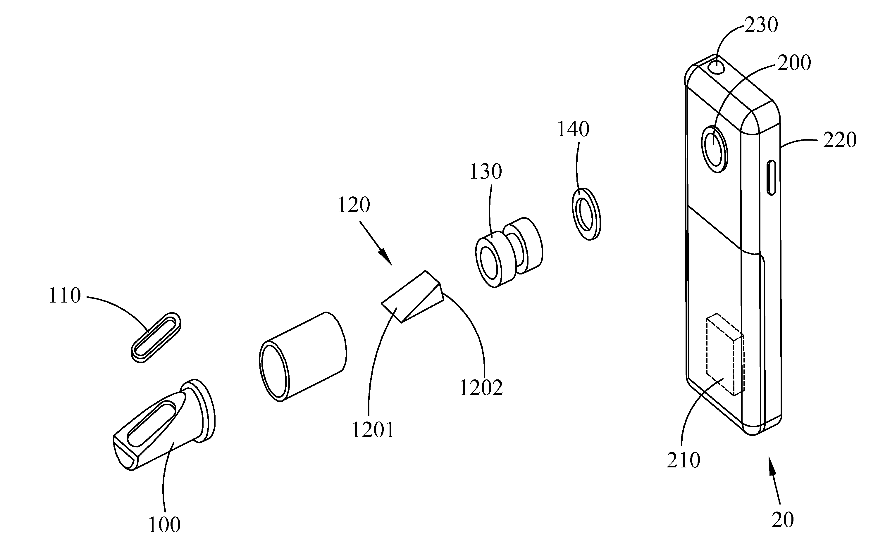
[0026]With reference to FIG. 4, in which a flow diagram of the image-based diopter measuring system according to the present invention is depicted. In the figure, first, the user switches on the image capture module 200 of the electronic device 20 to capture the light passing the analyte which is disposed in the optical device 10, and gather the external light via the analyte to generate the first image. The first image is a color two-dimensional image g(x,y) received by the image analyze module 210 which includes RGB three color components. A second image may be obtained after the image analyze module 210 executes the image pixel color conversion by a pixel conversion formula. The second image is a grayscale image h(x,y), the grayscale value is ranged from 0 to 255. After the image pixel color conversion is completed, the grayscale image is entered into the contrast line space coordinate detection unit 2110. The contrast line space coordinate detection unit 2110 conducts a convolut...


PUM


Abstract

An image-based diopter measuring system comprises an optical device and an electronic device. The optical device is used to guiding an external light which is passed through an analyte. The electronic device comprises an image capture module, an image analyze module and a display module. The image capture module generates a first image by capturing the external light source. The image analyze module connects to the image capture module to receive the first image, and analyzes the first image in order to generate an analytical result comprising the diopter of the analyte. The display module connects to the image analyze module to receive and display the analytical result.

Description

CROSS-REFERENCE TO RELATED APPLICATION[0001]This application claims the benefit of Taiwan Patent Application No. 102100988, filed on Jan. 10, 2013, in the Taiwan Intellectual Property Office, the disclosure of which is incorporated herein in its entirety by reference.BACKGROUND OF THE INVENTION[0002]1. Field of the Invention[0003]The present invention relates to a measuring system, in particular to an image-based diopter measuring system.[0004]2. Description of the Related Art[0005]Currently, the applications of the diopter are relatively extensive, for example, a sugar meter that measures the juice sweetness or measures the water salinity that both may use the diopter principle. The conventional sugar refractive index meter or the diopter in circulation such as the refractometers disclosed by Republic of China Patent D111526 or D127363. The refractometer is basically a round pipe body that a duckbill shaped portion of the front end is a measure end, which having a head shaped lift ...

Claims


Application Information

Patent Timeline
Patent Type & Authority Applications(United States)
IPC IPC(8): G01M11/02
CPCG01M11/0228G01N21/43
Inventor LIAO, TAI-SHANHUANG, CHI-HUNGWU, CHIH-CHIEHTSAI, DIN PINGCHOU, SHIH-JIEHO, CHENG-FANG
Owner NAT APPLIED RES LAB
Why Eureka
Try Eureka