Methods and apparatuses for channel measurement and feedback of multi-dimensional antenna array

a multi-dimensional antenna array and channel measurement technology, applied in the field of wireless communication, can solve the problems of affecting system performance, inability to efficiently use the channel measurement and feedback and inability to symmetrical uplink and downlink, so as to improve system performance, reduce measurement feedback overhead, and increase channel measurement accuracy of multi-dimensional antenna arrays

Inactive Publication Date: 2014-07-10
ALCATEL LUCENT SAS
View PDF7 Cites 78 Cited by
  • Summary
  • Abstract
  • Description
  • Claims
  • Application Information

AI Technical Summary

Benefits of technology

[0008]The core idea of the present invention is to allow a base station equipped with a multi-dimensional antenna array to configure more than one class of CSI-RS, wherein each class of CSI-RS is for use in the channel measurement at the UE for a different dimension of the multi-dimensional antenna array. The base station then transmits the generated configuration information to the UE, so that the UE may perform channel measurements specific to different dimensions (e.g., by selecting different codebooks for the channel measurement for different dimensions). In this way, it is possible to increase the channel measurement accuracy of the multi-dimensional antenna array, reduce the measurement feedback overhead and improve the system performance.

Problems solved by technology

However, in a modern communication system like a frequency-division demultiplexing (FDD) system, uplink and downlink are not symmetric due to frequency offset.
Therefore, the elevation angle estimation error might affect the system performance.
However, currently known standards are all designed and developed for the measurement and feedback of one-dimensional antenna arrays and thus cannot be efficiently used for the channel measurement and feedback of multi-dimensional antenna arrays.

Method used


Image

  • Methods and apparatuses for channel measurement and feedback of multi-dimensional antenna array
  • Methods and apparatuses for channel measurement and feedback of multi-dimensional antenna array
  • Methods and apparatuses for channel measurement and feedback of multi-dimensional antenna array

Examples


Embodiment Construction

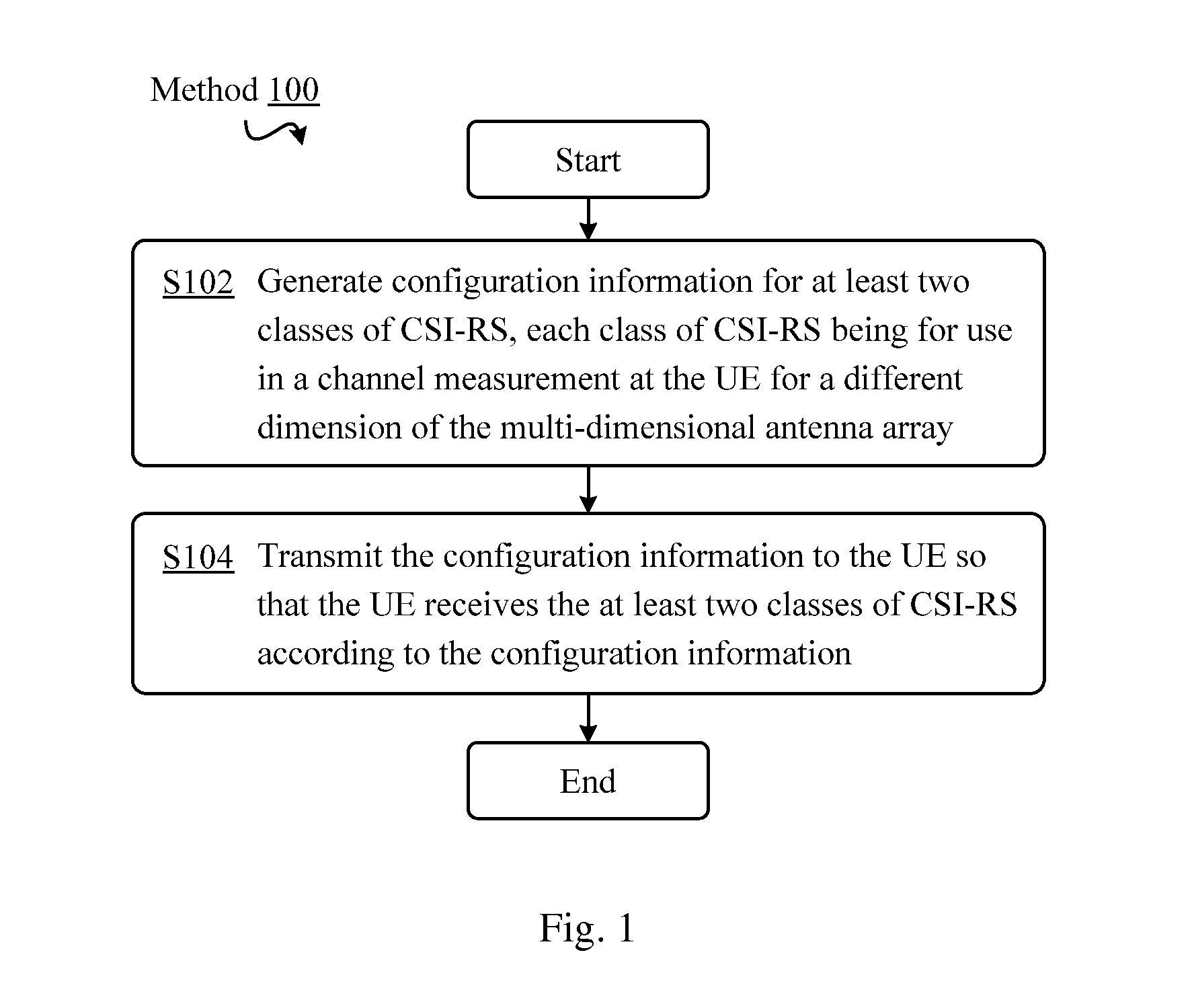
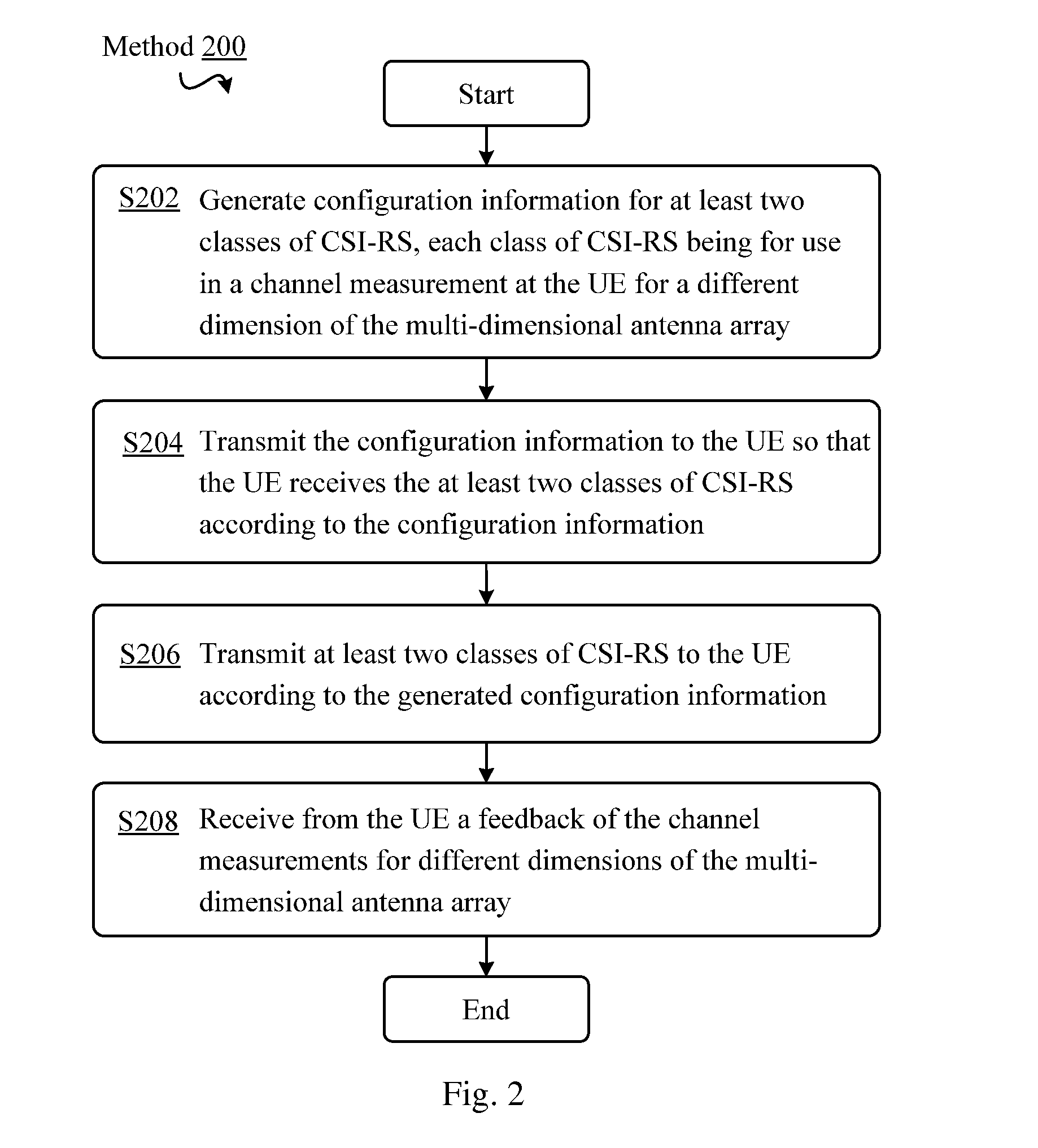
[0023]Detailed description will be presented below to embodiments of the present invention by referring to the figures. As described above and discussed below in detail, according to embodiments of the present invention, the base station equipped with a multi-dimensional antenna array is allowed to configure more than one class of CSI-RS, each class of CSI-RS will be used at the user equipment (UE) for a channel measurement for a different dimension of the antenna array. Subsequently, the base station may send the generated configuration information to the UE, allowing the UE to perform the channel measurement specific to different dimensions, for example, selecting different codebooks for the channel measurement for different dimensions. In this way, it is possible to increase the channel measurement precision of the multi-dimensional antenna array, lower the measurement feedback overhead and further improve the system performance.

[0024]It should be noted that in the context of the...


PUM


Abstract

Embodiments of the present invention generally relate to methods and apparatuses for the channel measurement and feedback of a multi-dimensional antenna array. Specifically, according to embodiments of the present invention, the primary inventive idea is to allow a base station equipped with a multi-dimensional antenna array to configure more than one class of CSI-RS, wherein each class of CSI-RS is for use in a channel measurement at the UE for a different dimension of the multi-dimensional antenna array. The base station then transmits the generated configuration information to the UE so that the UE may perform channel measurement specific to different dimensions, for example, by selecting different codebooks for the channel measurement for different dimensions. In this way, it is possible to increase the channel measurement precision of the multi-dimensional antenna array, reduce the measurement feedback overhead and improve the system performance.

Description

TECHNICAL FIELD[0001]Embodiments of the present invention generally relate to the wireless communication field, and more specifically, to methods and apparatuses for the channel measurement and feedback of a multi-dimensional antenna array.DESCRIPTION OF THE RELATED ART[0002]Long Term Evolution (LTE) / Long Term Evolution-Advanced (LTE-A) standard and system (e.g., LTE-A R10 system) of the 3rd Generation Partnership Project (3GPP) are defined and designed primarily for one-dimensional antenna arrays (e.g., uniform linear arrays) at present. In such standard and system, only azimuth angles of departure and arrival of an antenna signal on the horizontal plane are taken into consideration. In other words, in existing schemes, the design of system channel measurement and feedback is merely based on the single-dimensional antenna array assumption, which means only the horizontal signal propagation directivities are taken into account.[0003]However, in actual application environments, the a...

Claims


Application Information

Patent Timeline
Patent Type & Authority Applications(United States)
IPC IPC(8): H04L5/00H04W24/08
CPCH04W24/08H04L5/0051H04L1/0026H04L25/0204H04L25/03929H04W28/06H04B7/0486
Inventor LI, DONGWU, LUYANG, HONGWEI
Owner ALCATEL LUCENT SAS
Why Eureka
Try Eureka