
Method and system for data writing/reading onto/from and emulating a magnetic stripe

a magnetic stripe and data writing technology, applied in the field of smart cards, can solve the problems of limited data storage space, and limited use of smart cards, and achieve the effects of facilitating motionless card reading, reducing the number of conductors, and simplifying the associated electronics

Active Publication Date: 2009-09-22
INTELLECTUAL VENTURES HOLDING 81 LLC
View PDF3 Cites 229 Cited by
  • Summary
  • Abstract
  • Description
  • Claims
  • Application Information

AI Technical Summary

Benefits of technology

[0047]In accordance with an embodiment of the first aspect of the invention, there is provided an improved smart card accommodating a stationary bi-dimensional or multi-dimensional array, such as bi-dimensional matrix, without moving parts that selects writing (current flow) to each conductor by addressing at least two matrix coordinates utilized by the smart card. This matrix simplifies the complexity of the electronic drivers that inject current into each conductor segment. As will be explained in greater detail below, such reduced complexity leads to certain advantages, including reduced manufacturing and retail costs, as well as extending the product's battery lifespan.
[0056]In accordance with a third aspect of the invention there is provided a dynamic emulation of a magnetic stripe that facilitates motionless card reading. In accordance with this aspect, the smart card is positioned so that the magnetic field generated by the conductor is proximate to the magnetic read-head of a card reader. In accordance with this aspect, there is no need to swipe the card such that the magnetic stripe (or the magnetic field in case of static emulated magnetic stripe) traverses the read head of the reader. Accordingly, errors that stem from undue swiping of the card (and which occasionally require that the user should re-swipe the card) are avoided. As will be explained in greater detail below, in dynamic emulation the number of conductors is significantly reduced and the associated electronics is considerably simplified. The net effect is that manufacturing costs are significantly reduced and the smart card's battery lifespan is considerably extended.

Problems solved by technology

Notwithstanding the advantages of smart cards over magnetic cards, the adoption of smart cards has been relatively slow in the US and other leading markets.
One of the main reasons for their slow adoption is the present lack of support infrastructure (e.g. dedicated readers), necessitating retrofitting of equipment such as vending machines, ATMs, and telephones to incorporate dedicated readers that are adapted to read smart cards and possibly also write data thereon.
However, the lower the coercivity of the magnetic stripe material, the more susceptible is the magnetic stripe to being inadvertently modified by external magnetic fields.
One of the significant disadvantages of the smart card disclosed in the '659 publication is the use of a many conductors and a cumbersome electronic system including current drivers in order to facilitate data writing onto the magnetic stripe.
Such a cumbersome electronic system (as will be explained with greater detail below) poses high manufacturing costs and consumes battery power, thereby hindering the wide circulation into the marketplace of a smart card of the kind disclosed in the '659 publication.
This writing and flipping polarity is achieved at the cost of using a cumbersome system that includes 4 conductors and associated electronics per bit.
As may be recalled, relatively high currents are utilized since the higher the current, the stronger the generated magnetic field, thereby reducing the prospects of undesired flipping of the magnetic domain's polarity due to influence of external magnetic fields.
Realizing such a cumbersome system in a chip that is incorporated in a card having dimensions of a conventional credit card is relatively expensive, because the conductors and associated electronic circuitry would require relatively large real-estate chip space, rendering the manufacture of such chips expensive.
Note also that the more complicated the chip, the lesser the yield rate (i.e. the percentage of the fault free manufactured chips), giving rise to increased manufacturing costs, chip price, and the resulting smart card.
Note also that circuitry of the kind specified consumes battery power (due to the use of many current drivers, thus significantly reducing the lifespan of the card's battery, posing undue burden of the user who is compelled to frequently change or re-charge used batteries.

Method used


Image

  • Method and system for data writing/reading onto/from and emulating a magnetic stripe
  • Method and system for data writing/reading onto/from and emulating a magnetic stripe
  • Method and system for data writing/reading onto/from and emulating a magnetic stripe

Examples


Embodiment Construction

[0106]FIG. 17 illustrates schematically modules of a smart card in accordance with an embodiment of the invention.

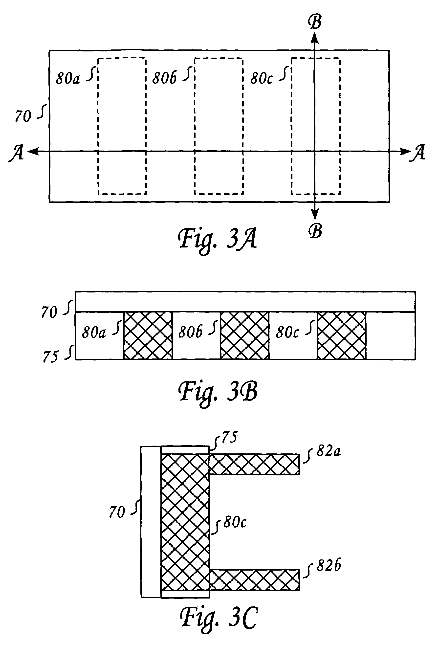
[0107]In accordance with a first aspect of the invention, there is provided a bi-dimensional or multi-dimensional conductor array that is proximate to the magnetic stripe that copes with the shortcomings of the hitherto known solutions. FIG. 4A illustrates a non-limiting embodiment of this aspect of the invention utilizing a matrix conductor array. It should be noted that the invention is not bound by any specific magnetic material that forms the magnetic stripe.

[0108]Thus, as shown, two substantially proximate conductors are associated to each domain, to allow a selection of each domain by the sum of currents in the two conductors. (As may be recalled, two domains constitute a single bit). Therefore, the sum of two currents flowing in the same direction is designed to overcome the coercivity of the magnetic stripe for each domain, whereas each current alone or two oppos...


PUM


Abstract

A method of writing data on magnetic stripe of a smart card by imposing a magnetic field of a given polarity on each selected segment of the magnetic stripe, such that data on the magnetic stripe can be read by a magnetic card reader and interpreted as digital bits. The method includes providing a multi-dimensional conductor array placed proximate to the magnetic stripe, the number of conductors in the array is considerably smaller than the number of segments, and each segment is associated with two or more conductors. The method further includes providing current drivers for sending currents in a controlled direction through the conductor array. The system further includes sending currents, using said current drivers, through conductors of the array, such that for each one of the selected segment composite currents flowing through its associated two conductors overcome the coersivity of the segment on the magnetic stripe.

Description

RELATED DATA[0001]The present application expressly incorporates by reference herein the entire disclosure of U.S. Provisional Application No. 60 / 464,123, entitled “Method and Apparatus for a data Writing onto and Emulating Magnetic Stripe”, which was filed on Apr. 21, 2003.FIELD OF THE INVENTION[0002]The present invention is generally in the field of improved smart cards.BACKGROUND AND RELATED INFORMATION[0003]The use of plastic cards bearing a magnetic stripe for effecting sales, banking, and other diverse transactions is very popular, in part because of the ease with which such cards may be legitimately used to effect these transactions, and because of the ubiquitous infrastructure that makes their use possible.[0004]A magnetic stripe on a card enables the card to be swiped repeatedly in a card reader and convey the digital information stored on the stripe to that reader. The information on a magnetic stripe is written onto the stripe by a magnetic write-head, similar to the way ...

Claims


Application Information

Patent Timeline
Patent Type & Authority Patents(United States)
IPC IPC(8): G06K7/08G06K1/12
CPCG06K19/06206G06K1/125
Inventor OSTERWEIL, JOSEFSHADMON, MOSHE
Owner INTELLECTUAL VENTURES HOLDING 81 LLC
Learn More