Methods and apparatus for automatic exposure control

an automatic exposure control and portable technology, applied in the direction of exposure control, optical radiation measurement, instruments, etc., can solve the problems of slowing down the decoding process, increasing the demand on the device, and limited decoding algorithms in such devices

Inactive Publication Date: 2006-12-12
HAND HELD PRODS
View PDF11 Cites 226 Cited by
  • Summary
  • Abstract
  • Description
  • Claims
  • Application Information

AI Technical Summary

Benefits of technology

[0016]The present invention is also defined by a method for exposure control in a multi-dimensional imaging device. The method comprises generating, at an imager, an end of frame signal and executing, at a central processor, a first module that controls exposure and gain settings in the imager in response to the end of frame signal. The first module then generates a captured contrast setting and the second module executes, at the central processor, by calculating a target contrast setting in response to the end of frame image signal, the captured contrast setting and stored image data. A subsequent (or new) exposure and gain setting is then generated in the first module in response to the target contrast setting. The subsequent exposure and gain settings are then implemented in the imager. The first module is typically implemented in a high priority routine, such as an interrupt service routine and the second module is typically implemented on a low priority routine such as a task level routine. In alternate embodiments, the processor that executes the first and second modules is additionally responsible for executing at least one imaging device appplication program and / or an image device operating system.

Problems solved by technology

As the use of such devices increases the demands on the devices will increase as well.
The decode algorithms in such devices are typically limited by the built-in exposure control of the imager (i.e. camera).
This limitation will generally slow down the decoding process and add inefficiency to the overall image capture and decode process.
However, implementing an exposure control mechanism that will provide accurate real-time exposure settings (i.e. automatic exposure control) under a multi-task operating system environment can be problematic.

Method used


Image

  • Methods and apparatus for automatic exposure control
  • Methods and apparatus for automatic exposure control
  • Methods and apparatus for automatic exposure control

Examples


Embodiment Construction

[0021]The present invention now will be described more fully hereinafter with reference to the accompanying drawings, in which preferred embodiments of the invention are shown. This invention may, however, be embodied in many different forms and should not be construed as limited to the embodiments set forth herein; rather, these embodiments are provided so that this disclosure will be thorough and complete, and will fully convey the scope of the invention to those skilled in the art. Like numbers refer to like elements throughout.

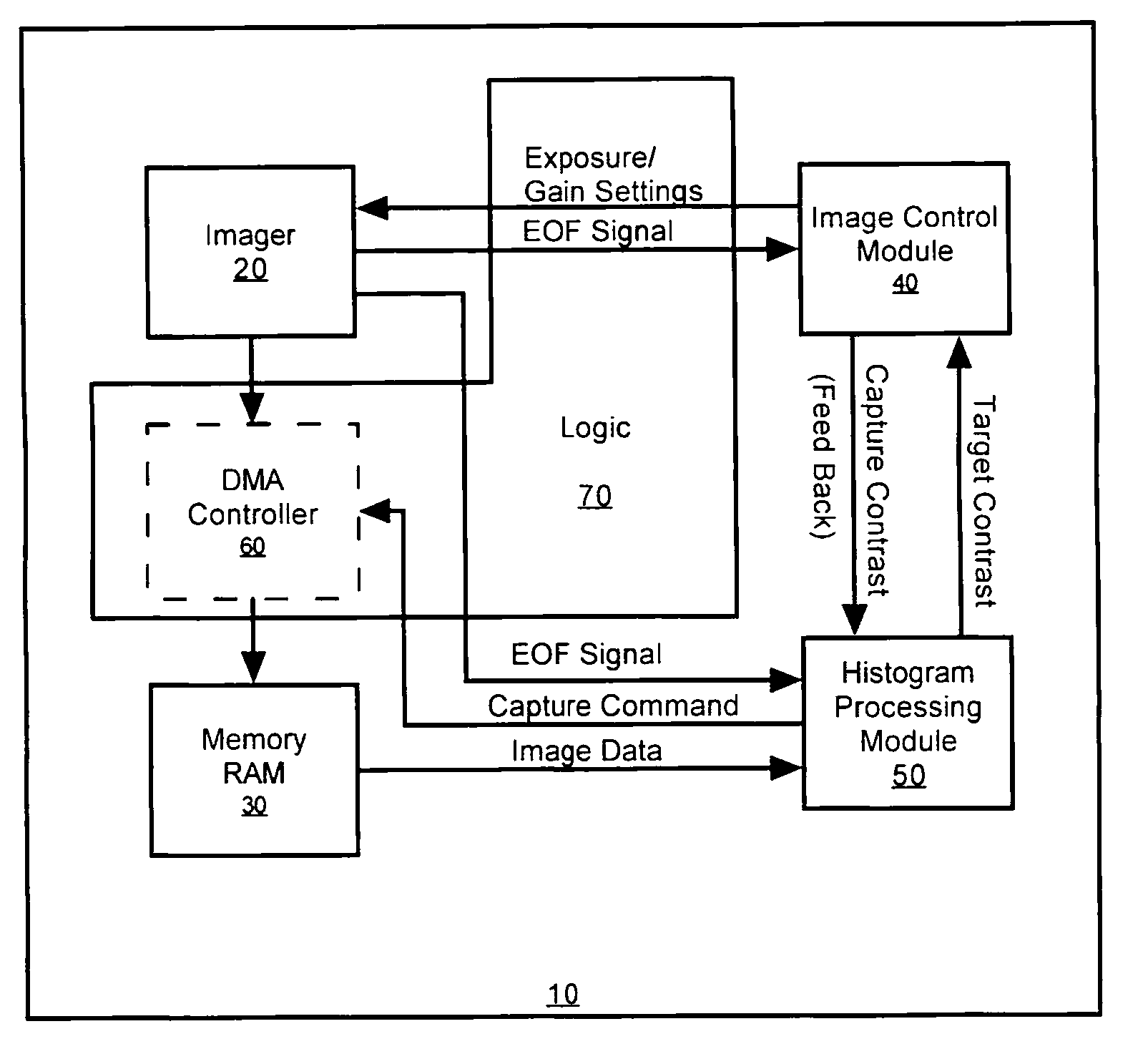
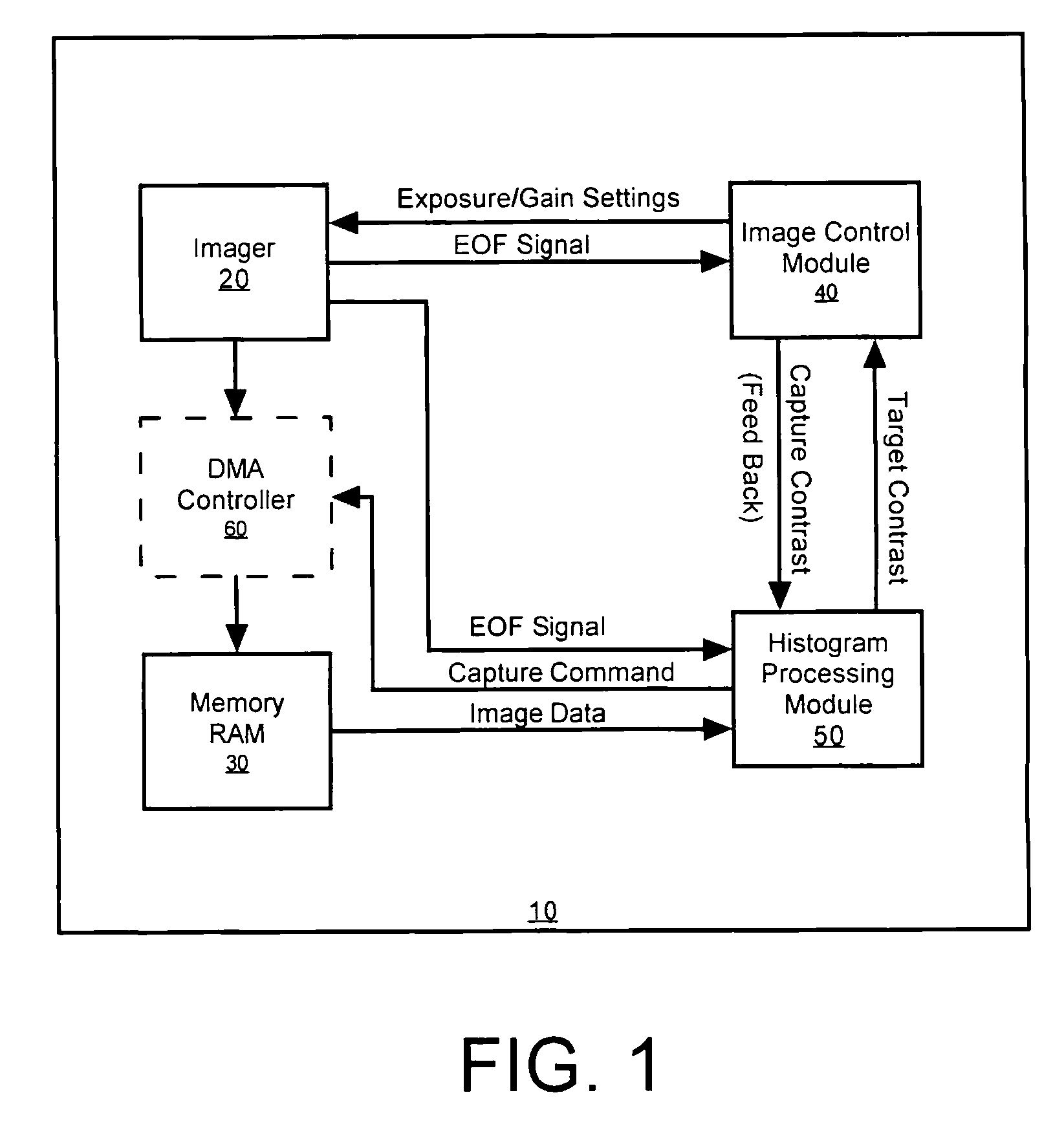
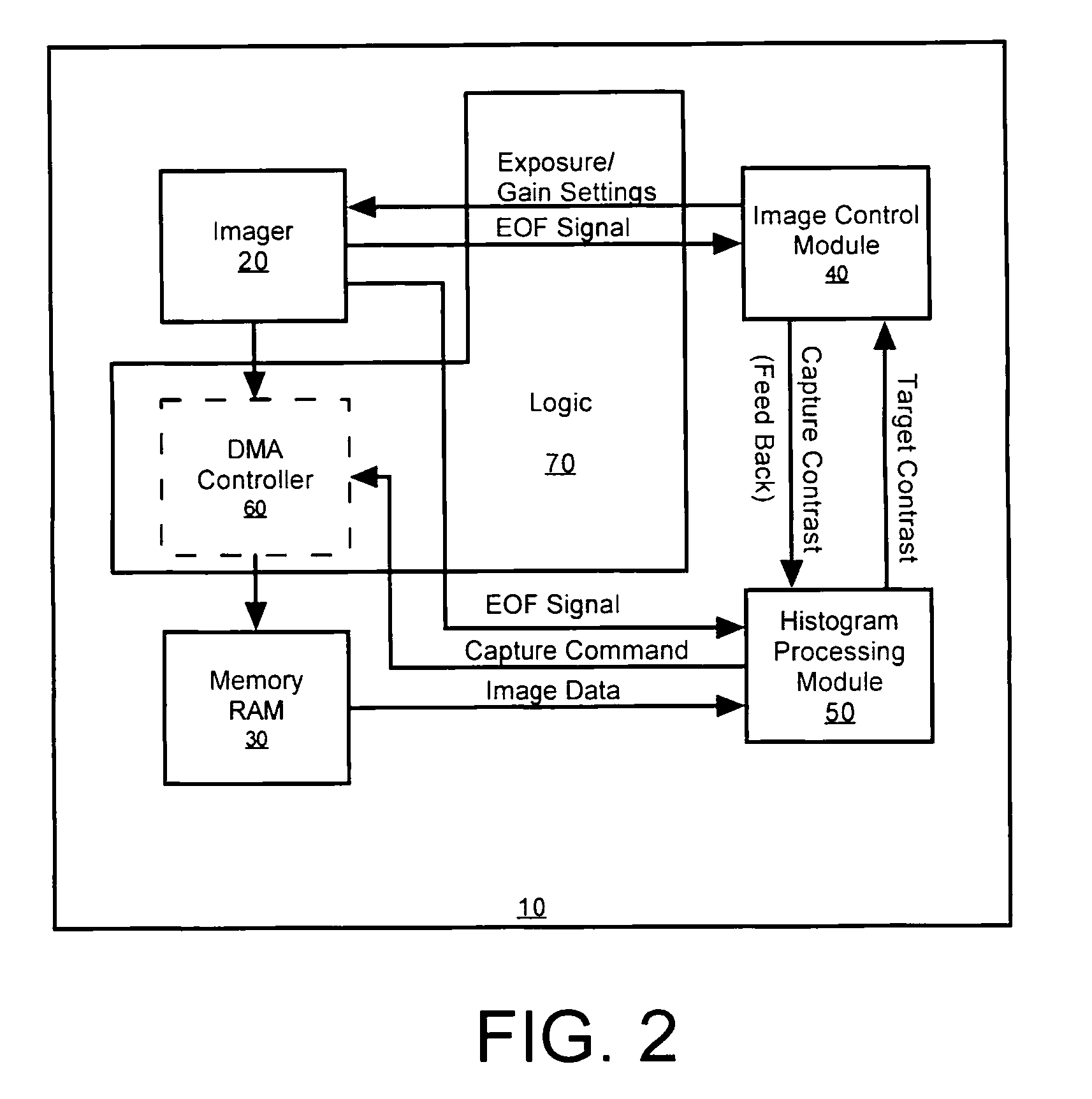
[0022]FIG. 1 is a block diagram that depicts the interaction between components in an imaging device incorporating automatic exposure control, in accordance with the present invention. The imaging device 10 comprises an imager 20, typically a camera that provides continuous image data to imaging device memory component 30, such as Random Access Memory (RAM). The imager will typically be capable of reading at least two-dimensional image symbologies, such as...


PUM


Abstract

A multi-dimensional imaging device and method for automated exposure control that implement two distinct modules to control the exposure and gain settings in the imager so that processing can occur in a multi-tasking single CPU environment. The first module, referred to herein as the imager control module, controls the exposure and gain settings in the imager. The first module is typically implemented in a high priority routine, such as an interrupt service routine, to insure that module is executed on every captured frame. The second module, referred to herein as the histogram processing module, calculates a target contrast (the product of the targeted exposure and gain settings) based on feedback data from the first module and image data from memory. The second module is typically implemented in a low priority routine, such as a task level routine, to allow for the routine to be executed systematically in accordance with priority.

Description

CROSS-REFERENCE TO RELATED APPLICATIONS[0001]The present application claims priority from U.S. Provisional Patent Application Ser. No. 60 / 237,063, filed Sep. 30, 2000, the contents of which are herein incorporated by reference.FIELD OF THE INVENTION[0002]The present invention relates to exposure control in a portable optical imaging device and more particularly to a method and apparatus for automatic, real-time, exposure control for an optical imager in a multi-dimensional optical imaging apparatus.BACKGROUND OF THE INVENTION[0003]Portable optical imaging devices such as bar code readers, optical character readers, digital cameras and the like have come into widespread use in large numbers of retail, industrial and medical applications. Such imaging devices are used to perform routine data entry functions such as pricing, inventory control, etc., with an accuracy and reliability that far exceeds that of manual data entry. These and other advantages, such as high data throughput rate...

Claims


Application Information

Patent Timeline
Patent Type & Authority Patents(United States)
IPC IPC(8): H04N5/235H04N5/225H04N1/024G06K7/10G06K9/00G03B7/28H04N5/351
CPCG06K7/10722G06K7/10752G06K7/1092
Inventor HARPER, JEFFREY D.HUSSEY, ROBERT M.PANKOW, MATTHEW W.MEIER, TIMOTHY P.
Owner HAND HELD PRODS
Why Eureka
Try Eureka