
Artificial turf

a technology of artificial turf and supporting surface, which is applied in the field of artificial turf systems, can solve the problems of increasing the cost of surface heat, reliance on routine field maintenance, and undesirable infill as the principal support surface, and achieves the effects of minimizing heat retention, low cost, and optimal performance characteristics

Inactive Publication Date: 2014-07-10
SPORTS FIELD HLDG
View PDF7 Cites 17 Cited by
  • Summary
  • Abstract
  • Description
  • Claims
  • Application Information

AI Technical Summary

Benefits of technology

The invention relates to an artificial turf that has the following benefits: it looks attractive, it helps to keep the surface cool, and it is easy and affordable to install. This makes it an ideal choice for use in sports arenas and playgrounds.

Problems solved by technology

The use of the infill as the principal support surface is undesirable for a multitude of reasons including, but not limited to, (i) inadequate performance due to inconsistency, instability as well as uneven force response and shock attenuation associated with the infill, (ii) the requirement of a greater infill depth, thereby increasing costs as well as surface heat, and (iii) the reliance upon routine field maintenance in order to periodically replace and / or redistribute the infill.
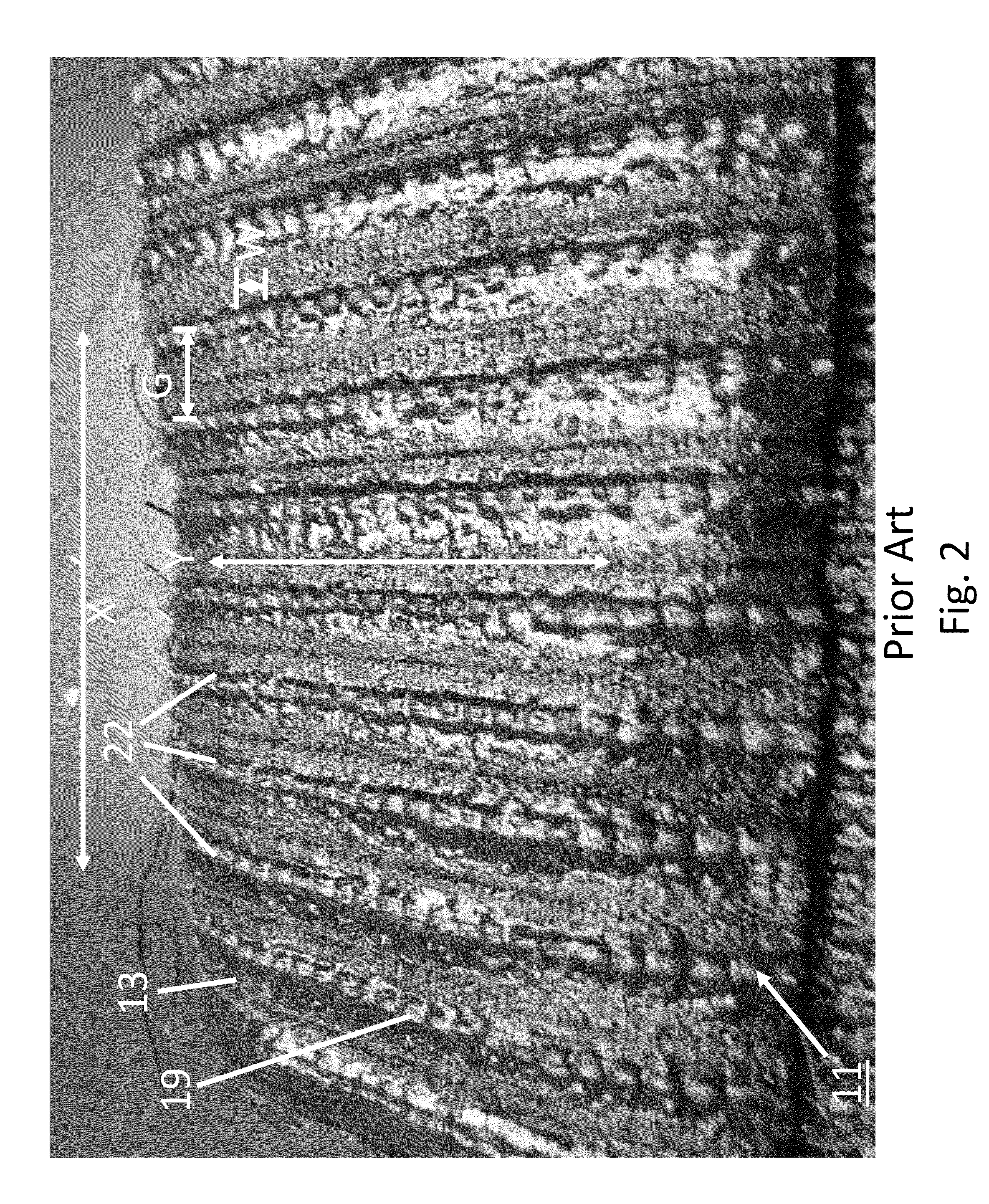
As a second shortcoming, the rectangular stitch construction of traditional artificial turfs creates an unpleasant appearance, which is often perceivable when viewed on high definition television.
Poor aesthetics result from, inter alia, perceivable stitch lines (often referred to in the art as “corn-rowing”) that result from using too wide a stitch gauge, visible displacement or “fly-out” of the poorly retained infill, and lay-over, or pile-crush, of the longer length and sparse arrangement of filaments (i.e., rather than extend in a near vertical orientation, the filaments tend to fold over, or flatten, into a near horizontal orientation, this condition often compromising performance as well as resulting in the unwanted retention of heat in the field surface).

Method used


Image

  • Artificial turf
  • Artificial turf
  • Artificial turf

Examples


Embodiment Construction

Construction of Artificial Turf 111

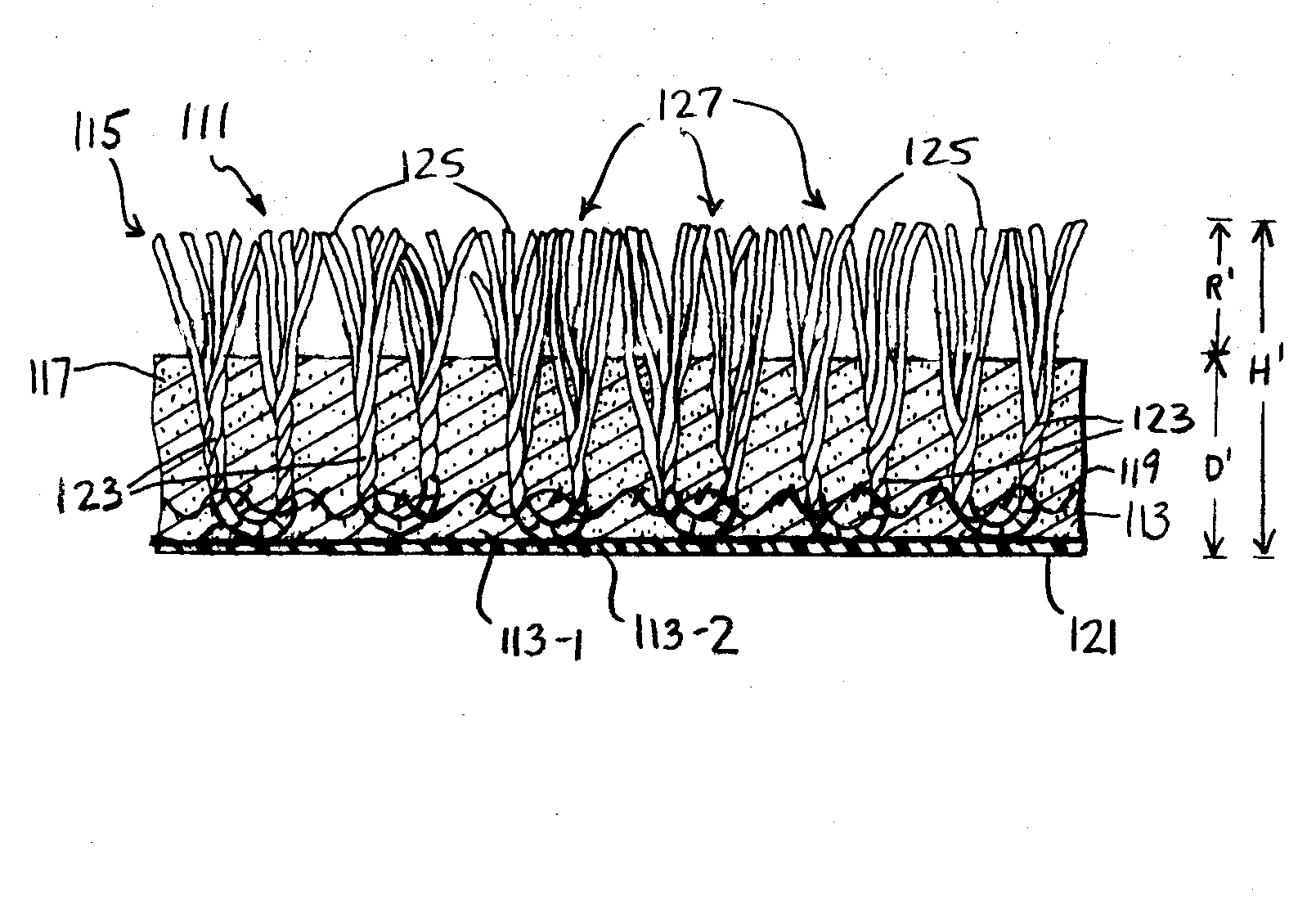
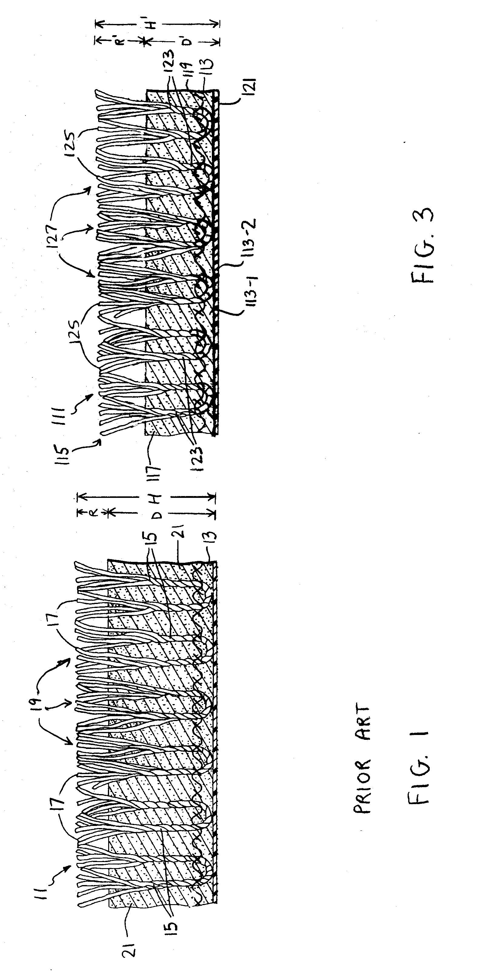
[0028]Referring now to FIGS. 3 and 4, there is shown an artificial turf constructed according to the teachings of the present invention, the artificial turf being identified generally by reference numeral 111. As will be described in detail below, artificial turf 111 relies upon a square stitch construction which, in turn, provides a number of notable advantages.

[0029]As seen most clearly in FIG. 3, artificial turf 111 is similar to prior art turf 11 in that artificial turf 111 comprises a flexible backing 113, a pile fabric 115 woven into backing 113, and a granular infill 117 deposited within voids formed in pile fabric 115.

[0030]Backing 113 is preferably constructed as a unitary, water-permeable member that supports pile fabric 115 and infill 117, backing 113 including a top surface 119 and a bottom surface 121 which is preferably disposed in direct contact against a horizontal drainage blanket (not shown). It is to be understood that backing 11...


PUM


Abstract

An artificial turf for a synthetic field system includes a flexible, water-permeable backing, a pile fabric woven into the backing, and a limited layer of water-absorbent, eco-friendly and light reflective infill deposited within voids formed in the pile fabric. The pile fabric is constructed with a plurality of separate, upwardly standing, reduced height tufts, each tuft including a plurality of synthetic filaments that resemble individual blades of natural grass. The tufts are arranged into parallel rows, with the spacing between rows being fixed and equal to the spacing between successive tufts in each row so as to yield an artificial field surface with an increased density of filaments. The dimensional aspects and high filament density of the artificial turf introduces a number of notable advantages over conventional artificial turfs including better performance, less surface heat retention, improved aesthetics, reduced infill maintenance requirements, and greater compliance with environmental standards.

Description

FIELD OF THE INVENTION[0001]The present invention relates generally to sports field playing surfaces and, more particularly, to artificial turf systems designed to replicate natural grass playing surfaces.BACKGROUND OF THE INVENTION[0002]Artificial, or synthetic, turf systems are well-known in the art and are commonly utilized as a low maintenance alternative to traditional grass field playing surfaces. Artificial turf systems typically comprise a firm, stable and impervious subsurface, or aggregate base, on which a water-permeable artificial turf is mounted. Preferably, a drainage blanket with a water impermeable barrier on its bottom surface is disposed between the stable subsurface and the artificial turf to promote lateral, or horizontal, drainage of water. Accordingly, rain is designed to readily penetrate through the artificial turf and into lateral channels formed in the drainage blanket which are then diverted horizontally to a drainage system in order to prevent saturation ...

Claims


Application Information

Patent Timeline
IPC IPC(8): E01C13/08
CPCE01C13/08
Inventor DALUISE, DANIEL A.
Owner SPORTS FIELD HLDG
Learn More