Construction of a multicarrier signal

a multi-carrier signal and construction technology, applied in the direction of orthogonal multiplex, multiplex communication, multi-frequency code system, etc., can solve the problems of requiring the use of a guard interval, affecting the efficiency of the system, and many drawbacks of the known system

Inactive Publication Date: 2001-08-21
SOC CIV MICHEL ALARD +2
View PDF3 Cites 39 Cited by
  • Summary
  • Abstract
  • Description
  • Claims
  • Application Information

AI Technical Summary

Benefits of technology

Thus, an aim of the invention is to provide a digital signal designed to be transmitted or broadcast to receivers, that can be used to obtain better performance characteristics in non-stationary channels and especially in highly non-stationary channels.
This makes it possible to provide for optimal performance characteristics in the non-stationary channels.

Problems solved by technology

These known systems have many drawbacks and limits, especially in very disturbed channels and when high efficiency is required.
The main problem of the OFDM / QAM system is that it imperatively requires the use of a guard interval.
As indicated here above, this gives rise to a substantial loss of efficiency when high spectral efficiency values are aimed at.
Furthermore, the signals sent out are poorly concentrated in the frequency domain, which also limits the performance characteristics in the highly non-stationary channels.
In particular, this spread makes it difficult to use equalizers.
Conversely, the frequency performance characteristics of the OFDM / OQAM are rather satisfactory and the problem of the loss related to the guard interval does not arise.
This implies two types of difficulties.
First of all, it is difficult to truncate the waveform in a short interval of time.
This implies complex processing in the receiver.
In other words, the efficiency of the OFDM / OQAM techniques is greater than that of the OFDM / QAM techniques, but these techniques prove to be more complicated to implement and therefore costly, especially in receivers.

Method used


Image

  • Construction of a multicarrier signal
  • Construction of a multicarrier signal
  • Construction of a multicarrier signal

Examples


Embodiment Construction

5.1. List of Figures

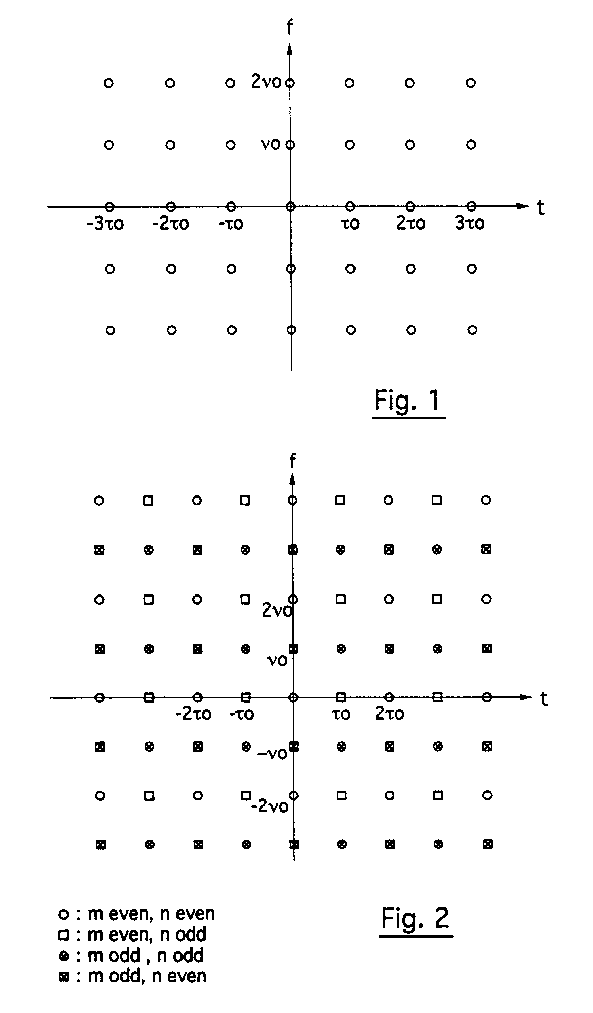
FIG. 1 illustrates a lattice with a density 1, corresponding to the one implemented in the case of the known OFDM / QAM modulation;

FIG. 2 illustrates a lattice with a density 2, corresponding to the one implemented in the case of the known OFDM / OQAM modulation, and in the case of the invention;

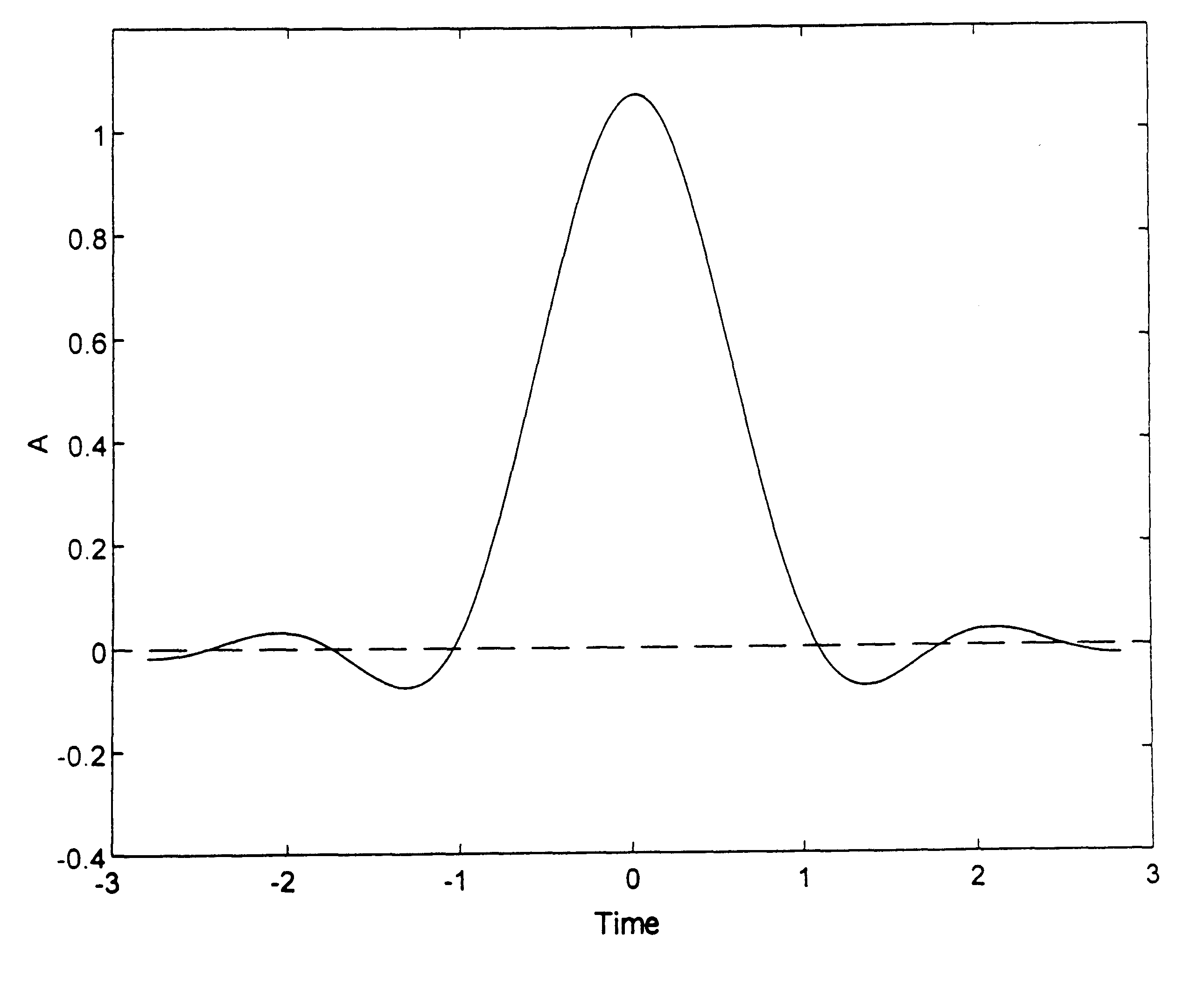
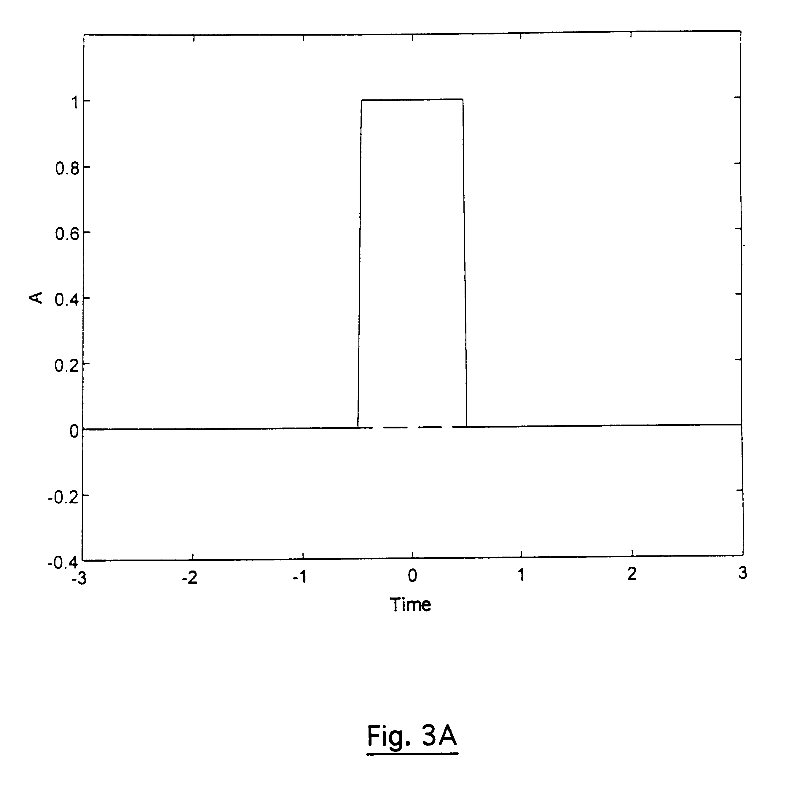
FIGS. 3A to 3D, 4C to 4D, 5A to 5D, 6A to 6D and 7A to 7D respectively show the known OFDM / QAM modulation (3), OFDM / QAM modulation with guard interval (4), OFDM / OQAM modulation (5) and the types of modulation used in the invention namely OFDM / MSK modulation (6) and OFDM / IOTA modulation (7), according to the following aspects:

A: the prototype function x(t);

B: the linear Fourier transform of the prototype function;

C: the modulus of the linear ambiguity function (as defined in Appendix 2);

D: the intersymbol function (as defined in Appendix 2);

FIG. 7E shows the decrease of the signal OFDM / IOTA in logarithmic scale;

FIG. 8 shows the ambiguity function of a Gaussian function;

FIG. 9 ...


PUM


Abstract

The invention concerns a multicarrier signal designed to be transmitted to digital receivers, especially in a non-stationary transmission channel, corresponding to the frequency multiplexing of several elementary carriers each corresponding to a series of symbols, two consecutive symbols being separated by a symbol time τ0, a signal in which, firstly, the spacing ν0 between two neighboring carriers is equal to half of the reverse of the symbol time τ0 and, secondly, each carrier undergoes an operation of filtering for the shaping of its spectrum having a bandwidth strictly greater than twice said spacing between carriers ν0 and is spectrum is chosen so that each symbol element is highly concentrated in the temporal domain and in the frequency domain.The invention also concerns the methods for the transmission and reception of such a signal.

Description

1. FIELD OF THE INVENTION1.1 General fieldThe field of the invention is that of the transmission or broadcasting of digital data, or of analog and sampled data, designed to be received in particular by mobile receivers. More specifically, the invention relates to signals produced by means of new forms of modulation as well as the corresponding techniques of modulation and demodulation.For many years now, it has been sought to build modulation schemes adapted to highly non-stationary channels, such as channels for transmission towards mobile receivers. In such channels, the signal sent out is affected by phenomena of fading and multiple paths. The work carried out by the CCETT within the framework of the European project EUREKA 147 (DAB: Digital Audio Broadcasting) has shown the value, for this type of channel, of multicarrier modulation (MCM) and especially of OFDM (Orthogonal Frequency Division Multiplexing).OFDM has been chosen within the framework of this European project as the ...

Claims


Application Information

Patent Timeline
Patent Type & Authority Patents(United States)
IPC IPC(8): H04L27/26H04L27/00H04J11/00
CPCH04L27/0004H04L27/2698H04L27/264H04L27/2602H04L27/2654H04L27/26416H04L27/26025
Inventor ALARD, MICHEL
Owner SOC CIV MICHEL ALARD
Why Eureka
Try Eureka