
High-voltage, alternating current power supply

a technology of alternating current and power supply, which is applied in the direction of printed circuits, electrical components association, printed circuit non-printed electric components, etc., can solve the problems of inoperable power supply or other damage, unreliable and conventional high-voltage ac power supply of the type described in detail above, and achieves convenient assembly, low cost, and high reliability.

Active Publication Date: 2017-05-09
STATIC CLEAN INT INC
View PDF6 Cites 1 Cited by
  • Summary
  • Abstract
  • Description
  • Claims
  • Application Information

AI Technical Summary

Benefits of technology

The present invention provides a reliable power supply that is less susceptible to operational failure due to partial electrical discharge. It has optimal performance characteristics and is easy to assemble with a limited number of parts and is inexpensive to manufacture.

Problems solved by technology

As a first shortcoming, conventional high-voltage, AC power supplies of the type described in detail above have been found to be unreliable and prone to early operational failure.
If any dielectric material either (i) inadequately encapsulates electrical components along the supply path (e.g., due to imperfections in the block that create small air cavities) or (ii) breaks down, or becomes otherwise damaged, a discharge of electricity can result in a shunt condition, which may render the power supply inoperable or otherwise damaged.
However, it has been found that both of the aforementioned techniques are rather cost-prohibitive to implement in static neutralization applications.
As a second shortcoming, conventional high-voltage, AC power supplies of the type described in detail above have been found to be limited in performance.
In particular, the use of a transformer with a laminated core often results in oversaturation, which in turn limits the rise and minimizes the peak elevation of the output voltage under load.
As a third shortcoming, conventional high-voltage, AC power supplies of the type as described in detail above have been found to be rather rigid in design and difficult to assemble.
Most notably, the inclusion of the relatively large, encapsulating, dielectric block renders the assembly process rather costly (due to the customized geometry of each block), time-consuming (to accommodate for the lengthy curing period of the encapsulating material) and structurally inflexible in nature.
This enlargement, or clearance, of each opening in the chassis results in small air gaps between the output port, or socket, for each output connector and the wall of the housing in which it is located.
As referenced above, the presence of air gaps along the voltage supply path can result in partial electrical discharge, which in turn can degrade selected electrical components and / or dielectric materials (e.g., the encapsulating block or potting compound).

Method used


Image

  • High-voltage, alternating current power supply
  • High-voltage, alternating current power supply
  • High-voltage, alternating current power supply

Examples


Embodiment Construction

Construction of Power Supply 111

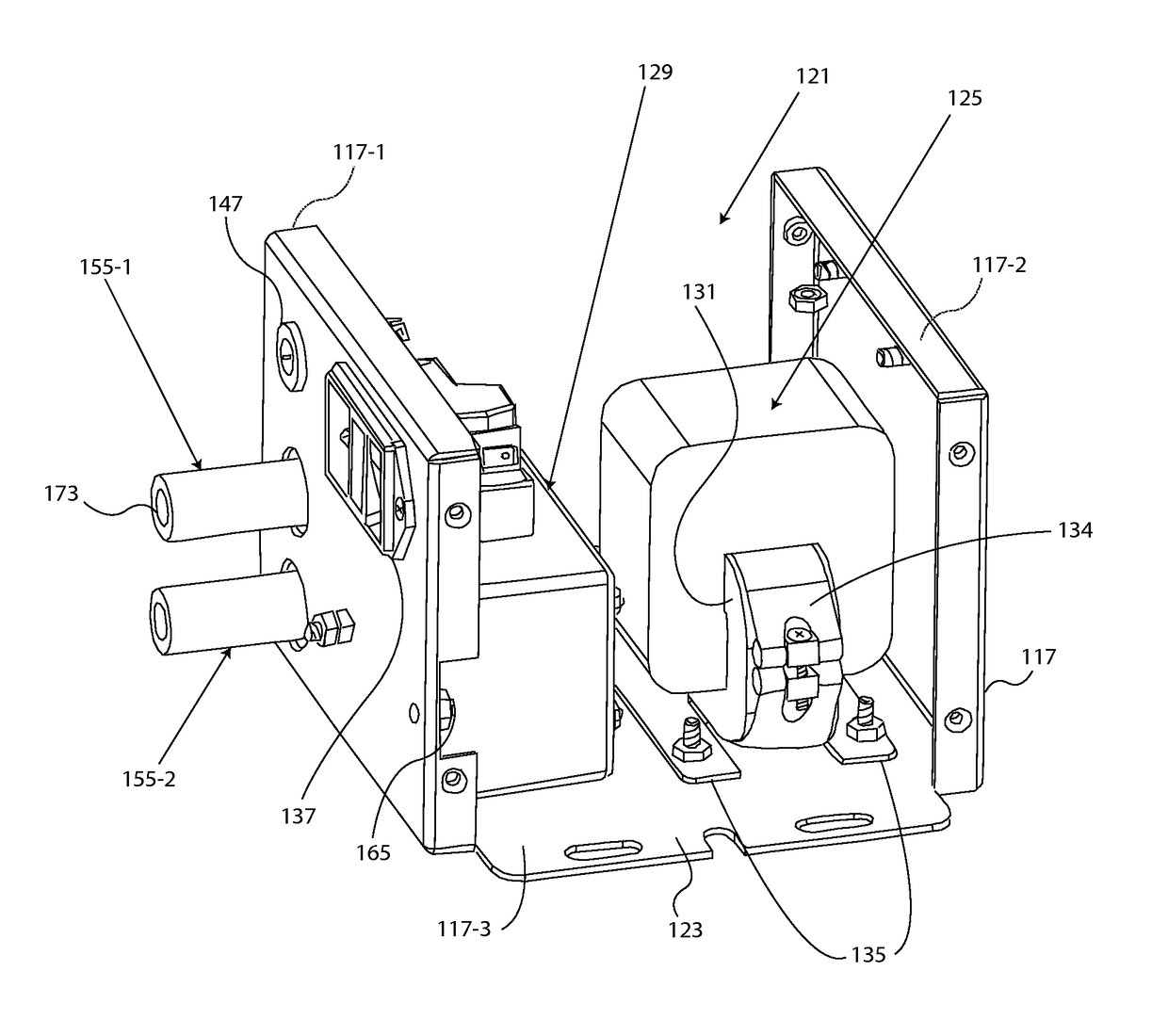
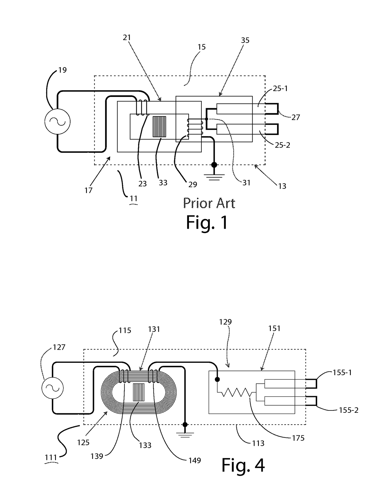
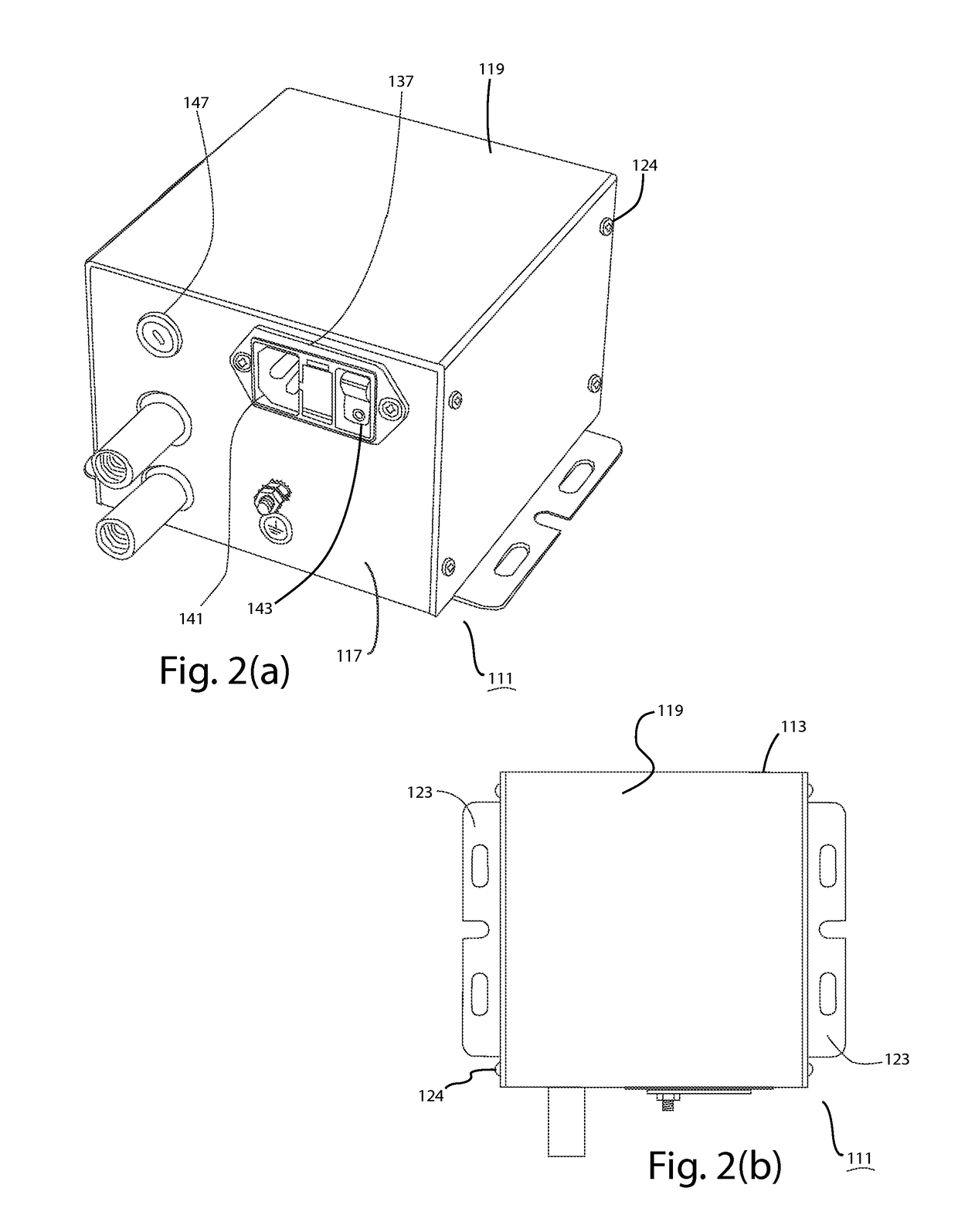
[0028]Referring now to FIGS. 2(a), 2(b), 3 and 4, there is shown a high-voltage, alternating current (AC) power supply that is constructed according to the teachings of the present invention, the power supply being identified generally by reference numeral 111. As will be described in detail below, power supply 111 is designed to provide high-voltage, AC power to an electrical device connected thereto.

[0029]Due to its particular set of performance characteristics, power supply 111 is particularly well suited for use in static neutralization systems, with power supply 111 providing high-voltage, AC power to one or more anti-static bars connected thereto. However, it is to be understood that power supply 111 is not limited to use in static neutralization systems, but rather, could be utilized in other systems that require the delivery of high-voltage, AC power without departing from the spirit of the present invention.

[0030]Power supply 111 comprises an...


PUM


Abstract

A high-voltage, AC power supply for an electrostatic discharge system comprises a chassis shaped to define an interior cavity, a high-voltage transformer for increasing the voltage received from an external power source, and an output connector module in electrical connection with the transformer for delivering the increased voltage to a high-voltage load, such as one or more anti-static bars. The transformer and the output connector are independently mounted onto the chassis within the interior cavity in a spaced apart relationship and are electrically coupled through one or more flying lead connectors in order to facilitate assembly. During operation, a resistive damping component in the output connector module regulates the output voltage and secondary current delivered to the load in order to render the power supply less susceptible to dielectric breakdown from partial discharge.

Description

FIELD OF THE INVENTION[0001]The present invention relates generally to power supplies and, more particularly, to high-voltage, alternating current (AC) power supplies that are commonly utilized in static neutralization systems.BACKGROUND OF THE INVENTION[0002]Static neutralization systems are well known in the art and are commonly utilized at various stages of product fabrication and packaging to remove potentially interfering, electrostatic charges from materials that readily develop static electricity, such as paper and plastic. Conventionally, static neutralization systems operate by emitting a field of positive and negative ions that neutralize any electrostatic charge present on the treated material.[0003]Static neutralization systems typically comprise one or more high-voltage, air-ionizing, anti-static electrodes, or bars, which are electrically coupled to a common, alternating current (AC) power supply capable of producing relatively high voltages (e.g., in the order of 7.5 ...

Claims


Application Information

Patent Timeline
Patent Type & Authority Patents(United States)
IPC IPC(8): H05K7/00H05K1/18H05K7/10H02M5/10
CPCH05K7/10H05K1/181H02M5/10H05K7/14322H05K7/1432
Inventor MACKILLOP, KENNETH MARTIN
Owner STATIC CLEAN INT INC
Learn More