Grounding structures for a receptacle assembly

a grounding structure and receptacle technology, applied in the direction of coupling device connection, electrical apparatus, coupling protective earth/shielding arrangement, etc., can solve the problems of insufficient electrical connectors, signal loss and/or signal degradation in known electrical systems, and further strain on performan

Inactive Publication Date: 2014-07-10
TE CONNECTIVITY CORP
View PDF10 Cites 30 Cited by
  • Summary
  • Abstract
  • Description
  • Claims
  • Application Information

AI Technical Summary

Problems solved by technology

However, as speed and performance demands increase, known electrical connectors are proving to be insufficient.
Signal loss and / or signal degradation is a problem in known electrical systems.
Such increase in density and / or reduction in size causes further strains on performance.
However, the shielding utilized in known systems is not without disadvantages.
For instance, electrically connecting the grounded components of the two electrical connectors at the mating interface of the electrical connectors is difficult and defines an area where signal degradation occurs due to improper shielding at the interface.
The ground shields may be at different electrical potentials and the signal contacts between the two ground shields are referenced to different electrical potentials, leading to signal degradation.

Method used


Image

  • Grounding structures for a receptacle assembly
  • Grounding structures for a receptacle assembly
  • Grounding structures for a receptacle assembly

Examples


Embodiment Construction

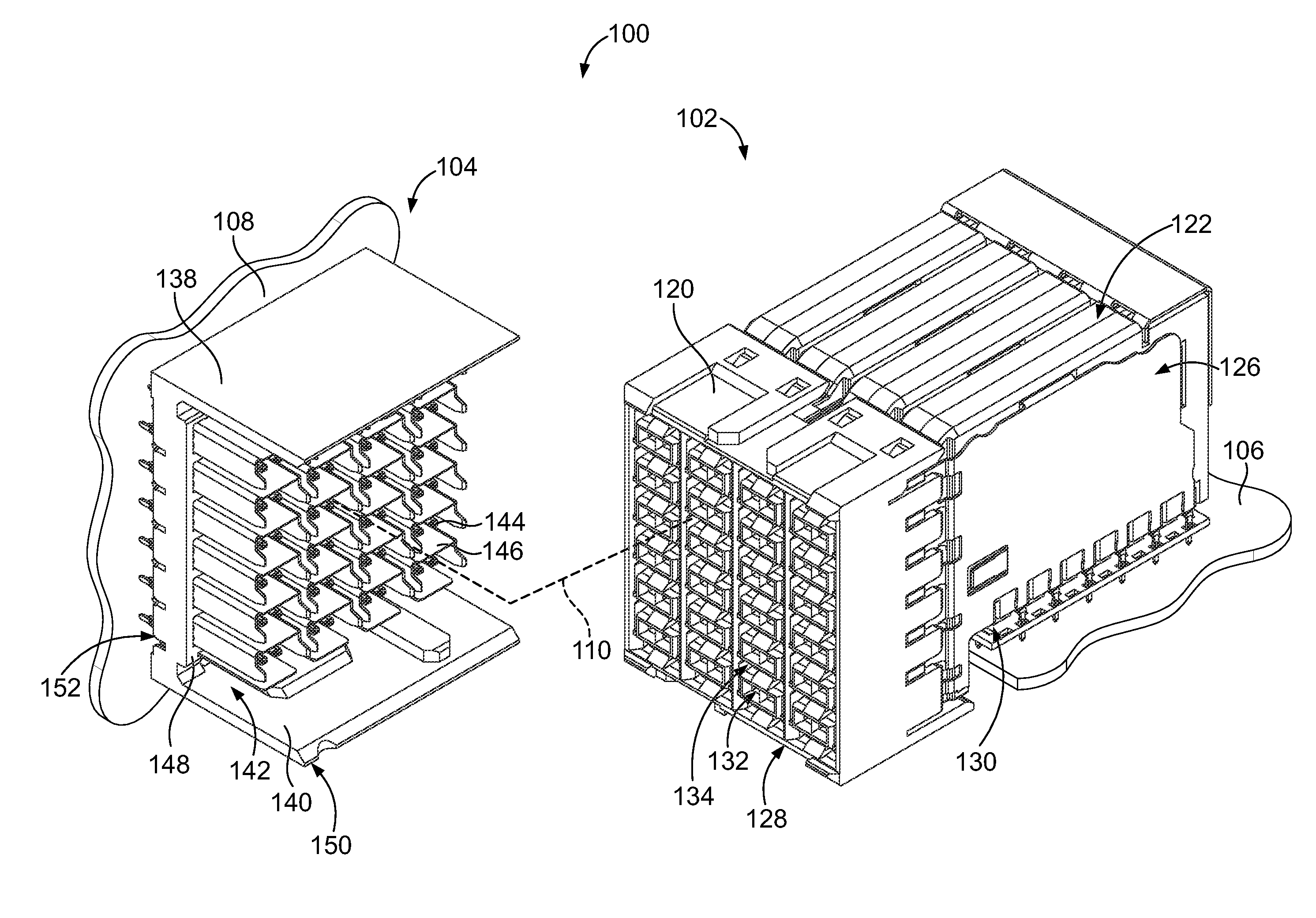
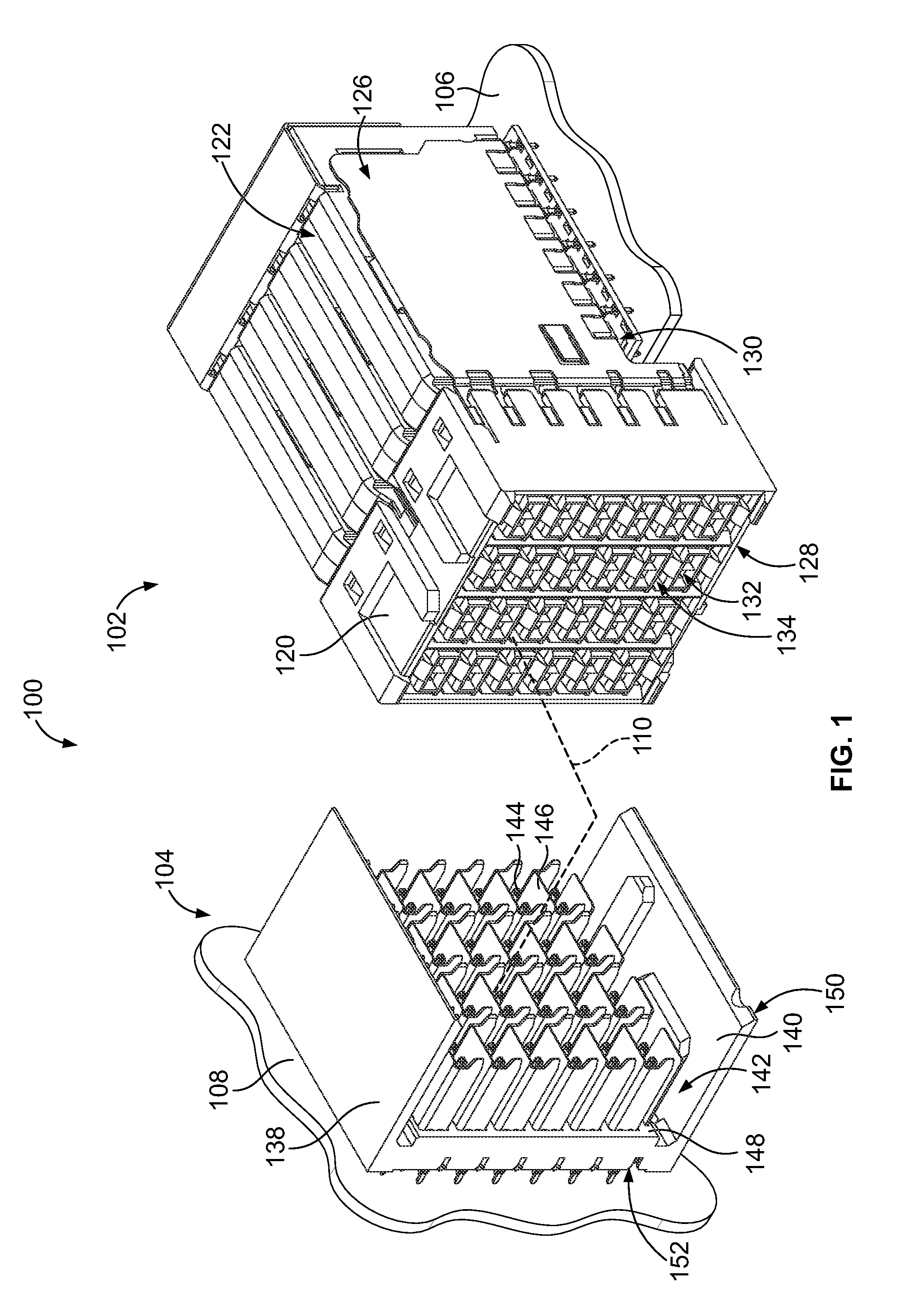
[0018]FIG. 1 is a perspective view of an electrical connector system 100 formed in accordance with an exemplary embodiment. The connector system 100 includes a receptacle assembly 102 and a header assembly 104 that may be directly mated together. The receptacle and header assemblies 102, 104 are each electrically connected to respective circuit boards 106, 108. The receptacle and header assemblies 102, 104 are utilized to electrically connect the circuit boards 106, 108 to one another at a separable mating interface. In an exemplary embodiment, the circuit boards 106, 108 are oriented perpendicular to one another when the receptacle and header assemblies 102, 104 are mated. Alternative orientations of the circuit boards 106, 108 are possible in alternative embodiments. Optionally, the receptacle and header assemblies 102, 104 may be mounted to cables and the like rather than the circuit boards 106, 108.

[0019]A mating axis 110 extends through the receptacle and header assemblies 102,...


PUM


Abstract

A receptacle assembly includes a contact module including a holder having a first side and an opposite second side. The holder holds a plurality of contacts. The contacts extend from the holder for electrical termination. A first ground shield is coupled to the first side. The first ground shield has grounding beams extending forward of the holder for electrical connection to a header assembly. The first ground shield has ground skewers extending into the holder. A second ground shield is coupled to the second side. The second ground shield has grounding beams extending forward of the holder for electrical connection to the header assembly. The second ground shield has ground skewers extending into the holder and the frame assembly. The ground skewers of the second ground shield engage and electrically connect to corresponding ground skewers of the first ground shield.

Description

BACKGROUND OF THE INVENTION[0001]The subject matter herein relates generally to grounding connector assemblies.[0002]Some electrical systems utilize electrical connectors, such as headers and receptacles, to interconnect two circuit boards, such as a motherboard and daughtercard. In some systems, to electrically connect the electrical connectors, a midplane circuit board is provided with front and rear header connectors on opposed front and rear sides of the midplane circuit board. Other systems electrically connect the circuit boards without the use of a midplane circuit board by directly connecting electrical connectors on the circuit boards.[0003]However, as speed and performance demands increase, known electrical connectors are proving to be insufficient. Signal loss and / or signal degradation is a problem in known electrical systems. Additionally, there is a desire to increase the density of electrical connectors to increase throughput of the electrical system, without an apprec...

Claims


Application Information

Patent Timeline
Patent Type & Authority Applications(United States)
IPC IPC(8): H01R13/648
CPCH01R13/648H01R12/727H01R12/737H01R13/514H01R13/6587H01R2107/00
Inventor PICKEL, JUSTIN DENNISSHARF, ALEX MICHAEL
Owner TE CONNECTIVITY CORP
Why Eureka
Try Eureka