System and method for calibration of a distributed amplifier system

a distributed amplifier and system technology, applied in the field of telecom systems, can solve the problems of rf loss variation and system performance reduction

Inactive Publication Date: 2014-07-10
WHOOP WIRELESS
View PDF4 Cites 19 Cited by
  • Summary
  • Abstract
  • Description
  • Claims
  • Application Information

AI Technical Summary

Problems solved by technology

In conventional telecommunication systems, RF losses between a head end and nodes of a system will decrease performance of the system.
Further, these RF losses can vary over time.

Method used


Image

  • System and method for calibration of a distributed amplifier system
  • System and method for calibration of a distributed amplifier system
  • System and method for calibration of a distributed amplifier system

Examples


Embodiment Construction

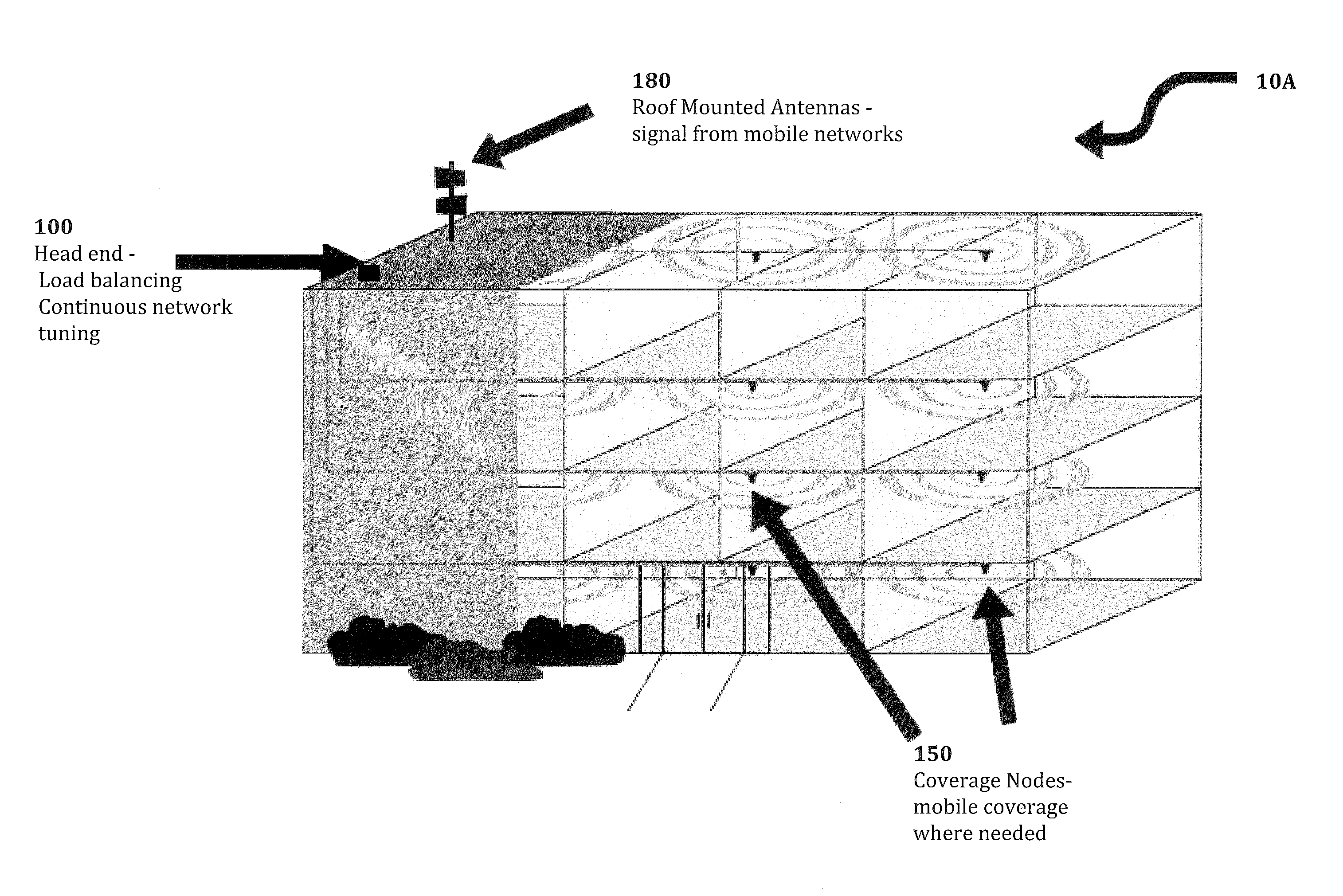
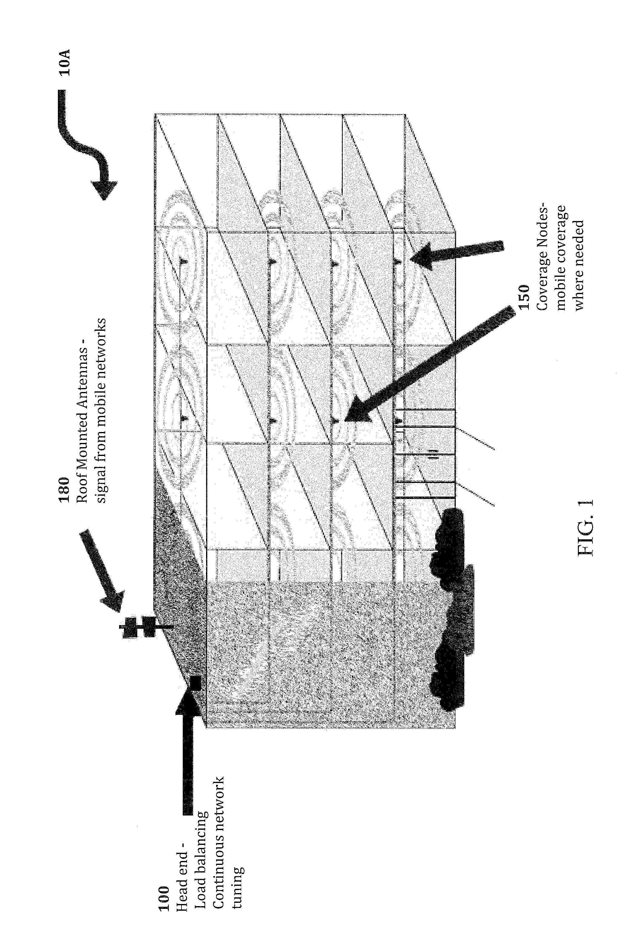
[0014]FIG. 1 is a diagram illustrating a deployment of a distributed amplifier system 10A. The cellular signals from outdoor cellular towers may not provide clear and consistent coverage inside buildings, so wireless operators and building owners use distributed antenna systems 10A to broadcast cellular signals throughout their facilities. The communications signals are distributed throughout building interiors, campus environments, and outdoor areas using an active Distributed Amplifier System. The DAS is active because it uses signal amplifiers to add gain to communications radio frequency (RF) signals. This gain also facilitates penetration of the signals throughout a building, campus environment, or outdoor areas despite physical obstructions such as walls, interior structures, poles, and trees without loss of signal integrity.

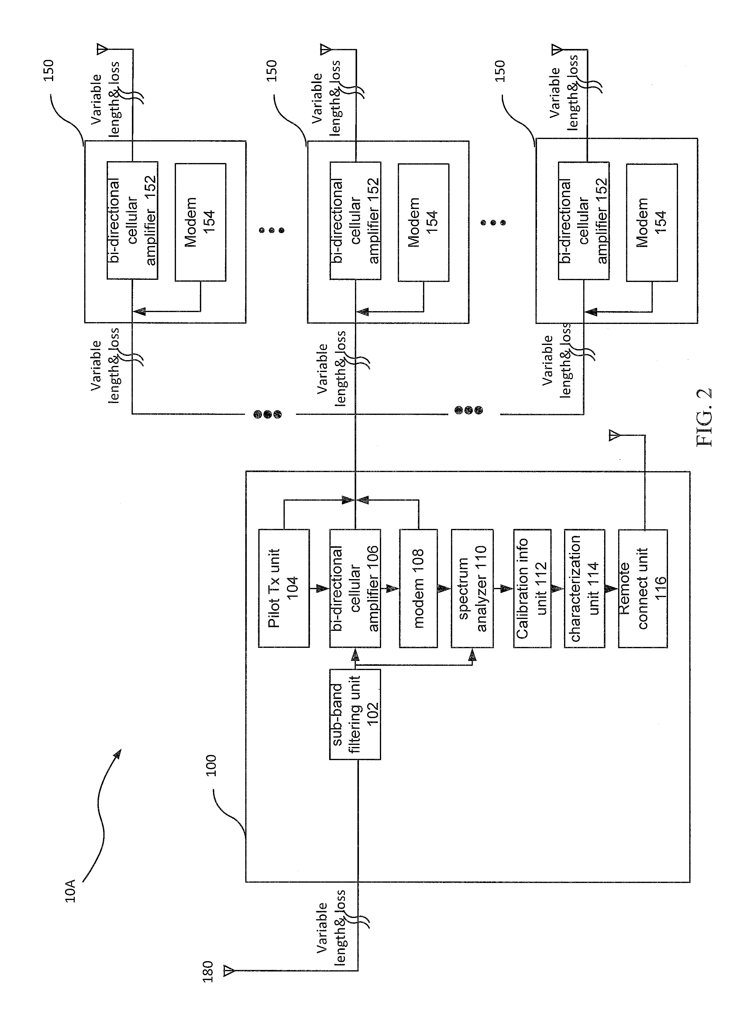
[0015]The distributed amplifier system comprises a head end 100, a plurality of coverage nodes 150 and roof mounted antenna(s) 180. The distributed amplif...


PUM


Abstract

A system and method in a distributed amplifier system for correcting for RF losses between head end and coverage nodes by measuring RF losses in both directions; generating gains for amplifiers in both the head ends and coverage nodes; generating maximum output power limits; and adjusting the generated gains and output power limits based on downlink signal strength of cellular signals at a donor antenna.

Description

CROSS-REFERENCE TO RELATED APPLICATION(S)[0001]The present application claims the benefit of and incorporates by reference U.S. provisional application No. 61 / 749,922, entitled “Intelligent Distributed Amplifier System,” which was filed on Jan. 8, 2013.TECHNICAL FIELD[0002]The present disclosure relates to a telecommunication system, and more particularly, but not exclusively to a system and method for calibrating a distributed amplifier system.BACKGROUND[0003]In conventional telecommunication systems, RF losses between a head end and nodes of a system will decrease performance of the system. Further, these RF losses can vary over time. Accordingly, a new system and method may be needed to calibrate the system over time to compensate for the RF losses.SUMMARY OF THE INVENTION[0004]In an embodiment, a method comprises measuring RF losses at multiple frequencies in both a first directions between a head end and a coverage node in a site by measuring output power from the head end and ...

Claims


Application Information

Patent Timeline
Patent Type & Authority Applications(United States)
IPC IPC(8): H04W52/24H04W24/10
CPCH04W24/10H04W52/245H03G3/20H04B1/16H04B17/318H04W16/26H04W24/02H04W24/08H04W52/52H04W88/085
Inventor TERRY, SCOTT
Owner WHOOP WIRELESS
Why Eureka
Try Eureka