
Method for controlling a vertical control system of a vehicle

a technology of vertical control system and control system, which is applied in the direction of cycle equipment, instruments, transportation and packaging, etc., can solve the problems of disadvantageous severe impairment of driving affecting the stability of the vehicle, and affecting the operation of the vehicle, so as to reduce the influence of the vehicle, and stabilize the driving stability

Inactive Publication Date: 2014-07-10
AUDI AG
View PDF7 Cites 14 Cited by
  • Summary
  • Abstract
  • Description
  • Claims
  • Application Information

AI Technical Summary

Benefits of technology

The present invention is related to a control system for vehicles. The technical effect of this invention is that it can prevent breakdowns of vehicles and increase safety during operation after detection of fault conditions. This is achieved by adjusting control parameters of multiple vertical control devices, which can compensate for the fault and restore full functionality of the vehicle. Additionally, an intervention in the control of the vehicle can be performed based on the detected fault condition, such as increasing braking force or reducing driving power, to further enhance safety during continued operation of the vehicle.

Problems solved by technology

Although fault conditions of conventional vertical control systems can be monitored, the driving stability of the vehicle is disadvantageously severely impaired when a fault conditions is detected.
In the worst case, this leads to a break-down of the vehicle, so that the defective vehicle must be towed to the next repair shop by a tow truck.
This may already occur when only a single vertical control device is faulty.
Accordingly, the complex vertical control systems having a variety of vertical control devices are significantly more error-prone, since a single fault condition can already cause a risk of the vehicle breaking down.
This significantly reduces the acceptance among users and also increases the traffic risk, because vehicles that have broken down can impede the traffic flow and endanger the users of the vehicle.

Method used


Image

  • Method for controlling a vertical control system of a vehicle
  • Method for controlling a vertical control system of a vehicle

Examples


Embodiment Construction

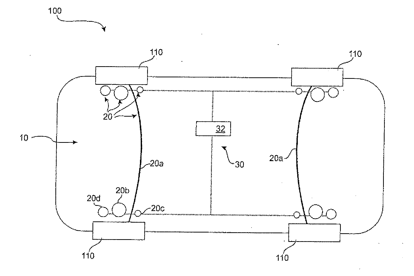
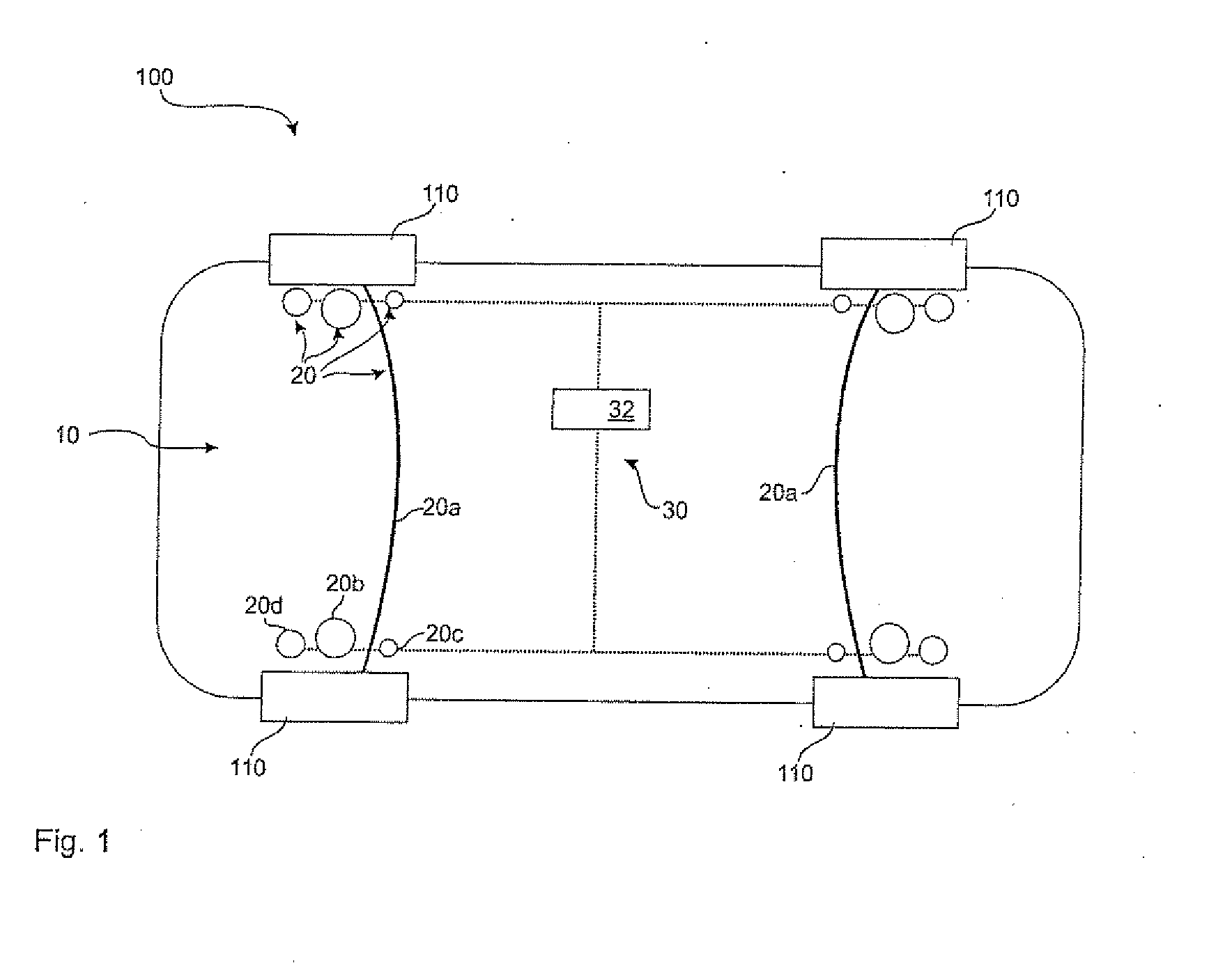
[0034]Throughout the Figure, same or corresponding elements may generally be indicated by same reference numerals. These depicted embodiments are to be understood as illustrative of the invention and not as limiting in any way. It should also be understood that the figures are not necessarily to scale and that the embodiments are sometimes illustrated by graphic symbols, phantom lines, diagrammatic representations and fragmentary views. In certain instances, details which are not necessary for an understanding of the present invention or which render other details difficult to perceive may have been omitted.

[0035]Turning now to FIG. 1, there is shown a vehicle 100 having a compensating device 30 according to the present invention. The vehicle 100 includes a vertical control system 10 with four different vertical control devices 20. A respective roll stabilization 20a is provided for the two axles, i.e. the front axle and the rear axle. This roll stabilization 20a connects the two wh...


PUM


Abstract

A method for controlling a vertical control system of a vehicle with at least two vertical control devices that influence the driving stability of the vehicle, includes monitoring the functionality of the at least two vertical control devices, detecting a fault condition of a first vertical control device of the at least two vertical control devices, and adjusting the control parameters of at least a second vertical control device of the at least two vertical control devices for at least partially compensating of the fault condition of the first vertical control device.

Description

CROSS-REFERENCES TO RELATED APPLICATIONS[0001]This application claims the priority of German Patent Application, 10 2013 000 360.1, filed Jan. 10, 2013, pursuant to 35 U.S.C. 119(a)-(d), the content of which is incorporated herein by reference in its entirety as if fully set forth herein.BACKGROUND OF THE INVENTION[0002]The present invention relates to a method for controlling a vertical control system of a vehicle, and a compensating device for controlling a vertical control system of a vehicle.[0003]The following discussion of related art is provided to assist the reader in understanding the advantages of the invention, and is not to be construed as an admission that this related art is prior art to this invention.[0004]It is known to equip vehicles with vertical control systems in order to variably adjust the driving stability and the driving dynamics. Vertical control systems include a variety of individual vertical control devices, which are known, for example, as air suspensio...

Claims


Application Information

Patent Timeline
IPC IPC(8): B60G21/00
CPCB60G21/00B60G17/0152B60G17/016B60G17/0185B60W10/22B60G2600/042B60G2600/044B60G2600/08B60G2800/80B60G2800/85B60G2800/912B60G2800/914B60G2800/915B60G2800/916B60W2050/0297
Inventor MULLER, ROLFKALTOFEN, JENSKOCH, TILOMILBREDT, PAUL
Owner AUDI AG
Learn More