Wire guide and flyer bow comprising said wire guide

Active Publication Date: 2014-07-17
SETIC
View PDF2 Cites 9 Cited by
  • Summary
  • Abstract
  • Description
  • Claims
  • Application Information

AI Technical Summary

Benefits of technology

[0043]By rejecting the teaching of U.S. Pat. No. '513, the present invention reduces not only wear of the cable but also its freedom to “flap” in the guide, therefor

Problems solved by technology

Problems have occurred as a result of the fact that, since the flyer bow rotates at very high speed and the cable is not fixed, the latter may collide with the grommet walls, thus causing fragility in the cable, even capable of breaking it.
In addition, the aerodynamics of the assembly comprising flyer bow, cable guide elements and cable is not absolutely optimum and, at the high speeds of rotation in question for the flyer bow, the resistance of the ambient air is very large

Method used


Image

  • Wire guide and flyer bow comprising said wire guide
  • Wire guide and flyer bow comprising said wire guide
  • Wire guide and flyer bow comprising said wire guide

Examples


Embodiment Construction

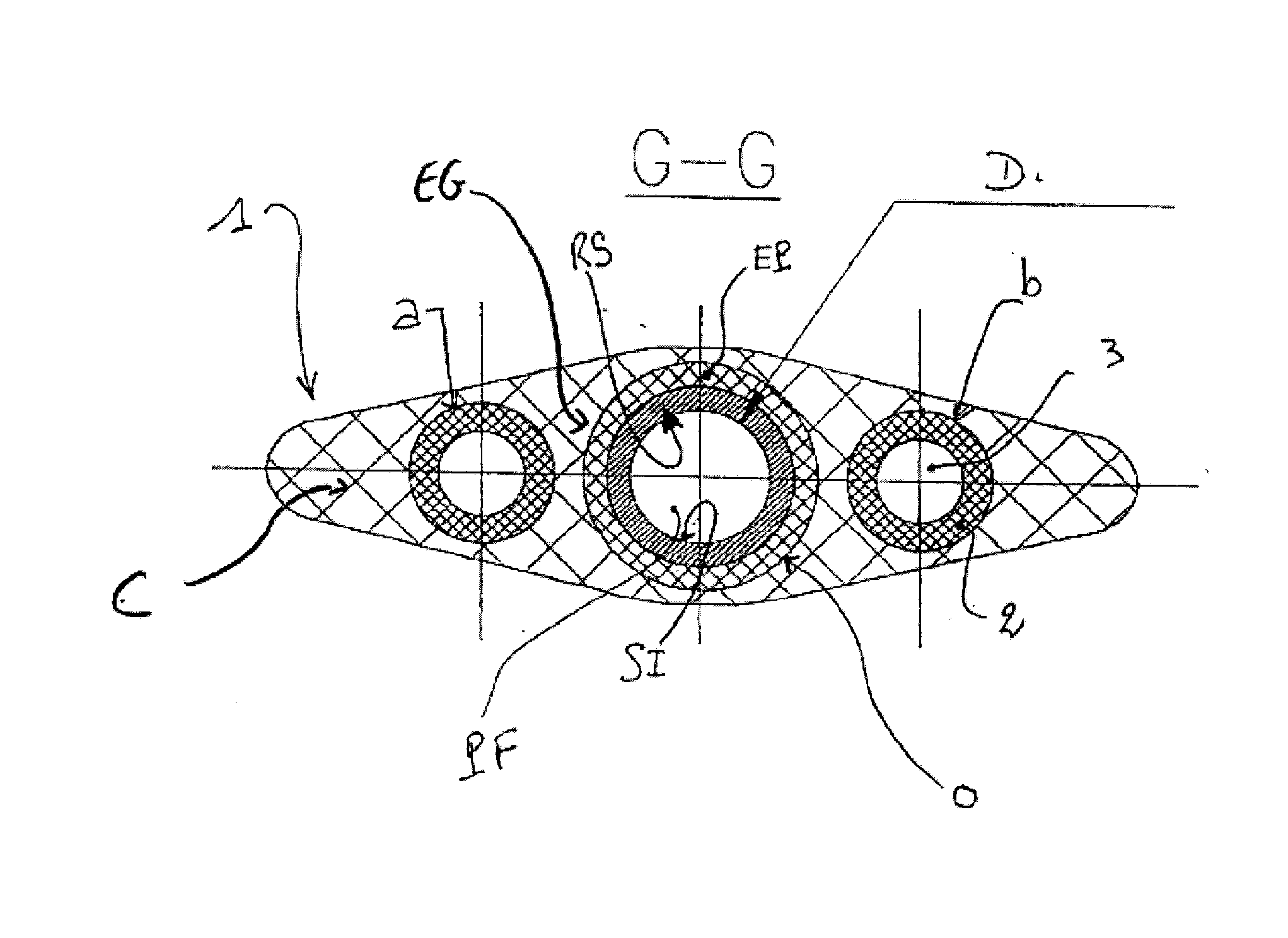
[0045]The invention therefore relates to a flyer bow of the type described hereinabove, the essential characteristic of which lies in a “cable” (wire, strand, cable, etc.) guide element for a flyer bow for assembling / twisting / braiding of “cable” surrounding the “cable” at least partly or completely with a body (C), the said flyer bow being provided with a longitudinal orifice or “internal tube” (O) made in the mass of the said body (C) and over the entire length of the said flyer bow. A “cable” guide element (EG) is accommodated in the said orifice (O) in order to guide the longitudinal travel of the “cable” therein. The said “cable” guide element (EG) presents its internal surface (SI) defining the “cable” channel (PF) formed by micro bulges (MB) alternating with “adjacent” micro hollows (MC).

[0046]Preferably the guide element (EG) completely surrounds the “cable”.

[0047]Such micro bulges (MB) and alternating “adjacent” micro hollows (MC) are represented on the attached FIG. 9.

[0048...


PUM

PropertyMeasurementUnit
Lengthaaaaaaaaaa
Lengthaaaaaaaaaa
Lengthaaaaaaaaaa

Abstract

A wire, strand, or cable guide element (EG) for a flyer bow for assembling/twisting/braiding the wire, strand, or cable has an inner surface (SI) which defines the travel path of the wire, strand, or cable (PF) and which consists of alternating adjacent micro-bumps (MB) and micro-recesses (MC). The flyer bow at least partially or entirely surrounds the wire, strand, or cable by means of a member (C) and has a longitudinal orifice or inner tube (O) in the mass of said member (C), said orifice or inner tube (O) extending along the entire length of the bow. The wire, strand, or cable guide element (EG) is accommodated within said orifice (O) so as to guide the longitudinal travel of the wire, strand, or cable.

Description

TECHNICAL FIELD[0001]The invention relates to the technical field of “rotating machinery” with flyer bow intended for assembly of cables and twisting of wires or strands, especially those permitting the production of double or triple twists (so-called “braiding” operations).[0002]It is recalled that this type of rotating machinery or flyer bow is well known to the person skilled in the art and is used in particular to twist individual wires to manufacture cables, especially cables intended to carry electricity, which require physical properties (tension, torsion, symmetry, etc.) of very high perfection.[0003]Throughout the present application, including the claims, the generic term “cable” will be used to designate the cable or wire or strand intended to run or “travel” as it is well known in or along the longitudinal surface of the flyer bow (all with appropriate “guide” means, themselves also known as regards their principle), the rotating flyer bow functioning to impress a twist ...

Claims


Application Information

Patent Timeline
IPC IPC(8): D07B3/10D07B7/02
CPCD07B7/02D07B3/103D07B2401/401D07B2501/406D07B7/021
Inventor BOUJAADA, MOSTAFAGIANONCELLI, DENISRONDEPIERRE, SOPHIE
Owner SETIC
Why Eureka
Try Eureka