Desiccant wheel dehumidifier and heat exchanger thereof

a technology of dehumidifier and heat exchanger, which is applied in the direction of heating types, domestic cooling devices, separation processes, etc., can solve the problems of increasing the production cost of heat exchangers and poor heat exchange performance, and achieves improved condensing performance, improved production efficiency, and large heat exchange area

Active Publication Date: 2014-07-17
NORM PACIFIC AUTOMATION
View PDF14 Cites 0 Cited by
  • Summary
  • Abstract
  • Description
  • Claims
  • Application Information

AI Technical Summary

Benefits of technology

[0010]According to the desiccant wheel dehumidifier and the heat exchanger thereof in one embodiment mentioned above, the exterior design of the plurality of heat exchange platy tube is a thin-wall hollow body, thus the plurality of heat exchange tubes can be made by means of resin extrusion molding, so as to improve production efficiency.
[0011]Furthermore, the plurality of heat exchange platy tubes can be arranged closely with appropriate intervals due to the platy shape, to provide a large heat exchange area within a limited space, thus improving the condensing performance.
[0012]In addition, the setting of the plurality of spacing walls can ensure that the plurality of heat exchange platy tubes still have a better structural strength with the shape of thin-wall hollow body, to avoid the plurality of heat exchange platy tubes from deformations during assembly.
[0013]Moreover, the structure design of the upper grille and the lower grille also makes the assembling of the heat exchange platy tubes easy, and prevents the leakage from the assembly clearances.

Problems solved by technology

But these heat exchange units cannot be closely arranged due to process limitations, so that the overall heat exchange area of the heat exchanger is small, resulting in a poor heat exchange performance.
Furthermore, for the structure of a conventional heat exchanger, it is inconvenient to assemble the heat exchange units, thereby increasing the production cost of heat exchangers.

Method used


Image

  • Desiccant wheel dehumidifier and heat exchanger thereof
  • Desiccant wheel dehumidifier and heat exchanger thereof
  • Desiccant wheel dehumidifier and heat exchanger thereof

Examples


Embodiment Construction

[0024]In the following detailed description, for purposes of explanation, numerous specific details are set forth in order to provide a thorough understanding of the disclosed embodiments. It will be apparent, however, that one or more embodiments may be practiced without these specific details. In other instances, well-known structures and devices are schematically shown in order to simplify the drawing.

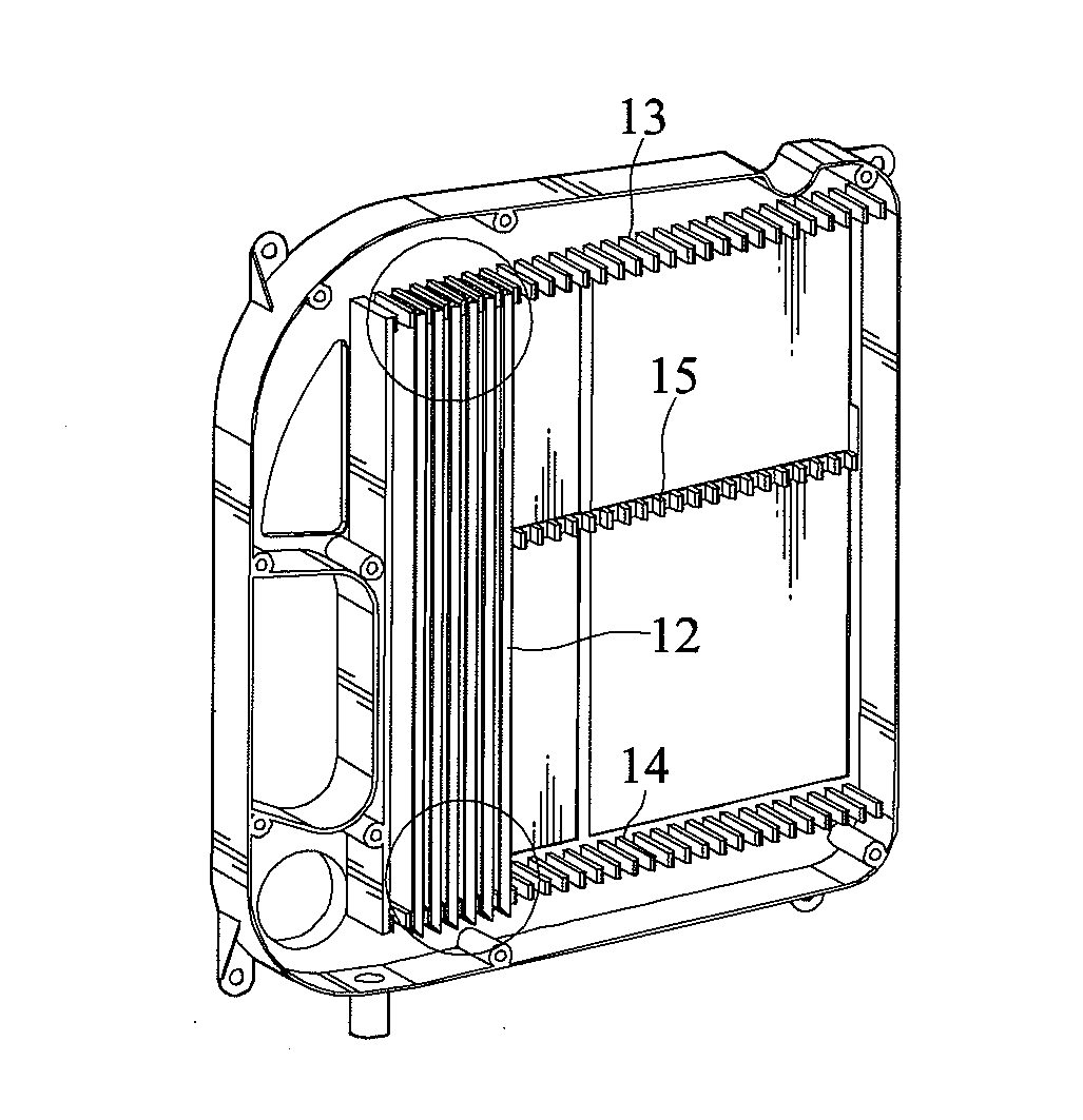
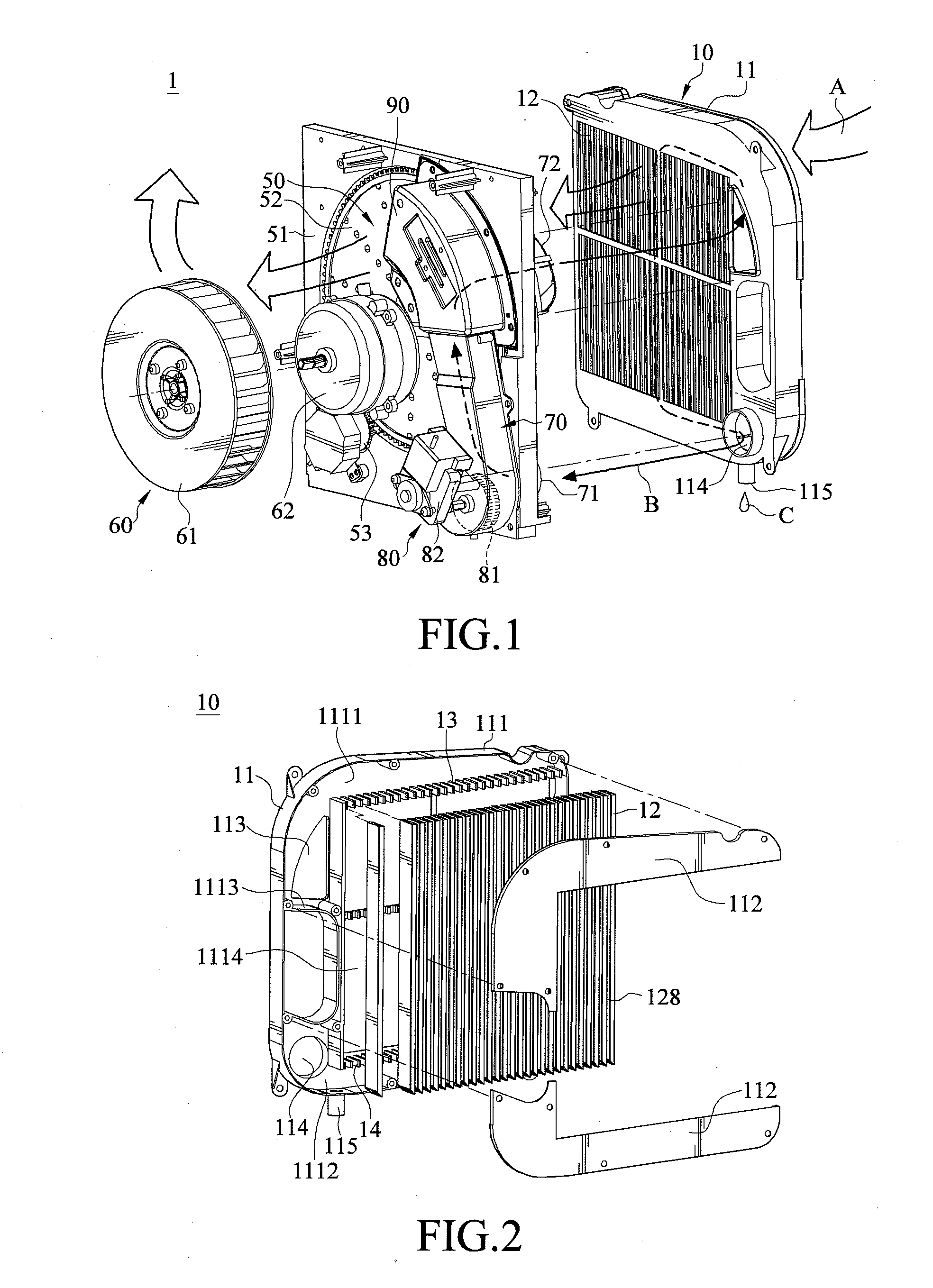
[0025]Please refer to FIG. 1, which is a structural exploded view of a desiccant wheel dehumidifier according to one embodiment of the disclosure.

[0026]A desiccant wheel dehumidifier 1 of this embodiment comprises a desiccant wheel module 50, a first airflow generation module 60, a circulating airflow duct 70, a second airflow generation module 80, a heater 90 and a heat exchanger 10.

[0027]The desiccant wheel module 50 comprises a base 51, a desiccant wheel 52 and a wheel motor 53. The base 51 is substantially a plate with a hole, the desiccant wheel 52 is adapted for being rotatabl...


PUM


Abstract

A heat exchanger of a desiccant wheel dehumidifier, disclosed in the disclosure, includes a frame and multiple heat exchange platy tubes. The frame has an air inlet and an air outlet. The multiple heat exchange platy tubes are fixed on the frame and are substantially arranged side by side with each other. Every two of the multiple heat exchange platy tubes adjacent to each other are separated at an interval from each other to form a first flow channel. Each of the multiple heat exchange platy tubes includes a main body and at least one spacing wall. The main body has multiple second flow channels therein. The at least one spacing wall is located between two of the multiple second flow channels adjacent to each other. The air inlet and the air outlet communicate with the multiple second flow channels.

Description

BACKGROUND[0001]1. Technical Field[0002]This disclosure relates to a dehumidifier and a heat exchanger thereof, and more particular to a desiccant wheel dehumidifier and a heat exchanger thereof.[0003]2. Related Art[0004]Generally, a desiccant wheel dehumidifier absorbs moisture from air by the use of a desiccant wheel that includes a main fan for blowing the indoor air passing through the moisture absorption materials, so that the air that is discharged from the dehumidifier is dry and the goal of indoor dehumidification is accomplished. The moisture absorbed by the desiccant wheel is evaporated by the use of heated air from an internal circulating air. The evaporated moisture then enters a heat exchanger to be condensed into water droplets, which are discharged from a water outlet.[0005]The heat exchanger, of the prior arts desiccant wheel dehumidifier, includes a plurality of heat exchange units, which are usually hollow pipelines. But these heat exchange units cannot be closely ...

Claims


Application Information

Patent Timeline
Patent Type & Authority Applications(United States)
IPC IPC(8): F28D1/02F24F3/14F28D1/053
CPCF28D1/024F28D1/0535F24F3/1411F24F3/1423F28D1/05383F28F1/025F28F9/0224B01D53/06B01D53/261
Inventor CHEN, CHIN-HUANHSU, HONG-YANGLIU, CHIA-LIANG
Owner NORM PACIFIC AUTOMATION
Why Eureka
Try Eureka