Solar Powered Iluminated Boat Cleat

Inactive Publication Date: 2014-07-17
HERMAN N PHILHOWER AS TRUSTEE OF THE H N PHILHOWER FAMILY TRUST LAST DATED OCTOBER 31 2012
View PDF4 Cites 4 Cited by
  • Summary
  • Abstract
  • Description
  • Claims
  • Application Information

AI Technical Summary

Benefits of technology

[0007]The present invention provides for an illuminated boat cleat that has a number of advantages over conventional non-lighted cleats as well as cleats which are specially installed and wired for energization by the power mains. First, by eliminating the need to connect to power mains, a corresponding savings is

Problems solved by technology

The risk of field service inconsistencies in environmental sealin

Method used


Image

  • Solar Powered Iluminated Boat Cleat
  • Solar Powered Iluminated Boat Cleat
  • Solar Powered Iluminated Boat Cleat

Examples


first embodiment

[0050]Referring to FIG. 5, a perspective view of the solar powered illuminated boat cleat as seen in FIGS. 1-4 better illustrates an overall view and illustrates the fasteners that hold the self contained solar powered modular structure in place. The a top set of securing screws 101 are seen as being set apart from the hex bolts 43. This means that the solar powered illuminated boat cleat 21 cannot be removed from the top, but only that the solar powered modular structure 25 may be able to be accessed. Securing screws 101 will preferably be made of stainless steel and will preferably have a security structure at the top to limit the ability of a passer-by or casual tool possessor from dislodging the solar powered modular structure 25.

[0051]Referring to FIG. 6, a top view of the of the solar powered illuminated boat cleat as seen in FIGS. 1-5 is shown and illustrates further details of the solar powered modular structure and upper hex bolts. Seen clearly for the first time are depres...

second embodiment

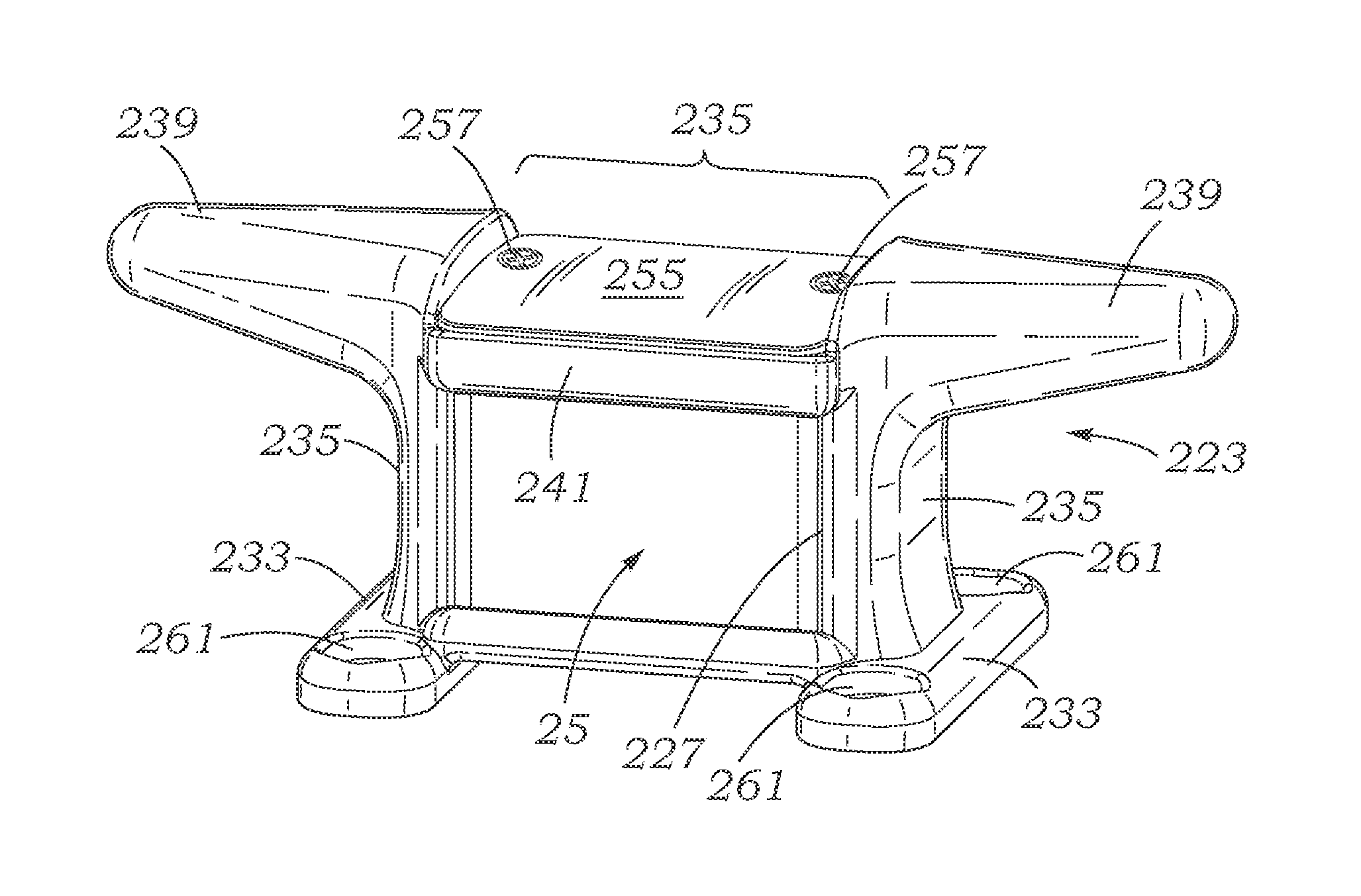
[0059]Referring to FIG. 9, a perspective view of the solar powered illuminated boat cleat of the invention which may typically be a smaller version, is shown as a solar powered illuminated boat cleat 221 and having a boat cleat mechanical housing support structure 223. Solar powered illuminated boat cleat 221 may utilize the same solar powered modular structure 25 with the same or greater capabilities than heretofore described. Solar powered illuminated boat cleat 221 may have a rectangular opening 227 adjacent a lens 31 of the solar powered modular structure 25. A pair of bases 233 each support a vertical structure 235. The vertical structures 235 demark a center section 237 between them which may contain the solar powered modular structure 25. The upper area of the vertical structures 235 naturally turn outward into a pair of cantilevered arms 239. A frame section 41 connects the pair of cantilevered arms 239. In between the frame section 41 and pair of cantilevered arms 239, a so...


PUM


Abstract

The boat cleats of the invention are typically mounted on the watercraft and docks adjacent to the water for tying watercraft to piers as well as to other watercraft and disclose a solar powered modular structure supported within a boat cleat mechanical housing support structure. This arrangement provides savings associated with the provision of through-the-dock wiring access, easy removability for replacement, maintenance and servicing, and which is sealed against the environment. The self contained solar powered modular structure may have communications capabilities to enable distributed control and sensing.

Description

[0001]Continuation of Provisional Patent No. 61 / 752,958 filed Jan. 15, 2013.FIELD OF THE INVENTION[0002]The present invention relates to improvements in the field of dock mounted support structures for providing stable support and for providing illumination in a manner that is low maintenance and with automatic operational service, and which will provide benefits to boat owners and dock managers by providing a constant night time illumination without the need for wiring.BACKGROUND OF THE INVENTION[0003]Dock mounted support structures, sometimes referred to as cleats, may typically be a pair of opposite projections supported above the surface of a dock or deck. Boats are moored to docks and piers utilizing boat cleats which may be more often mounted to docks, piers, but may even be found mounted to boat decks. Conventional boat cleats normally do not provide any means of lighting and if some form of lighting is supplied, such as adjacent to the cleat, such lighting is required to be ...

Claims


Application Information

Patent Timeline
IPC IPC(8): B63B45/00B63B21/04
CPCB63B21/045B63B45/00B63B2201/08B63B2209/18
Inventor ADAIR, ROBIN CHARLES
Owner HERMAN N PHILHOWER AS TRUSTEE OF THE H N PHILHOWER FAMILY TRUST LAST DATED OCTOBER 31 2012
Why Eureka
Try Eureka