
Tracheal tube system for enhanced patient comfort

a tracheal tube and patient technology, applied in the field of tracheal tubes, can solve the problems of patient discomfort, difficulty in securing the tracheostomy tube more comfortably to the patient, and difficulty in decoupling the tracheostomy tube from the patient neck, so as to improve comfort and comfort, and minimize patient sweat

Inactive Publication Date: 2014-07-17
TYCO HEALTHCARE GRP LP
View PDF4 Cites 2 Cited by
  • Summary
  • Abstract
  • Description
  • Claims
  • Application Information

AI Technical Summary

Benefits of technology

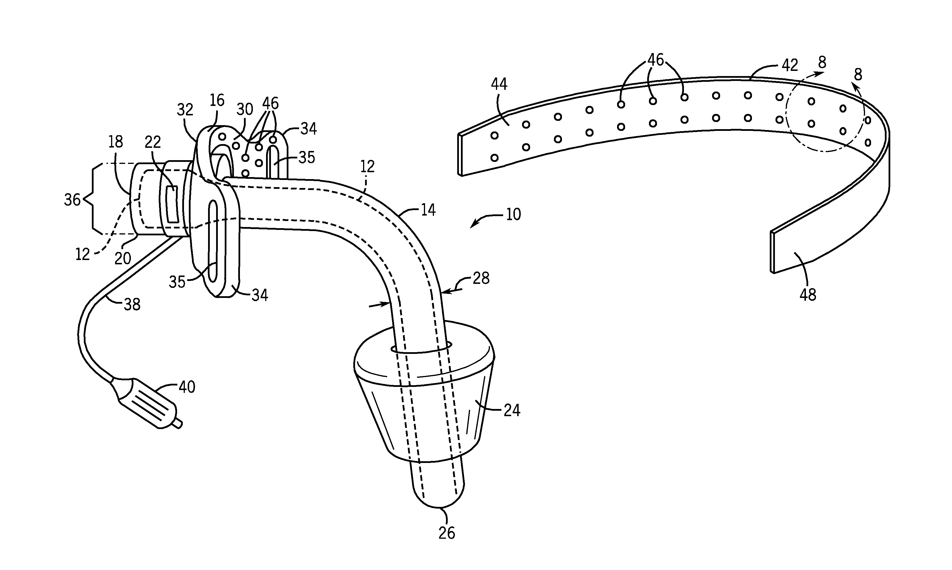
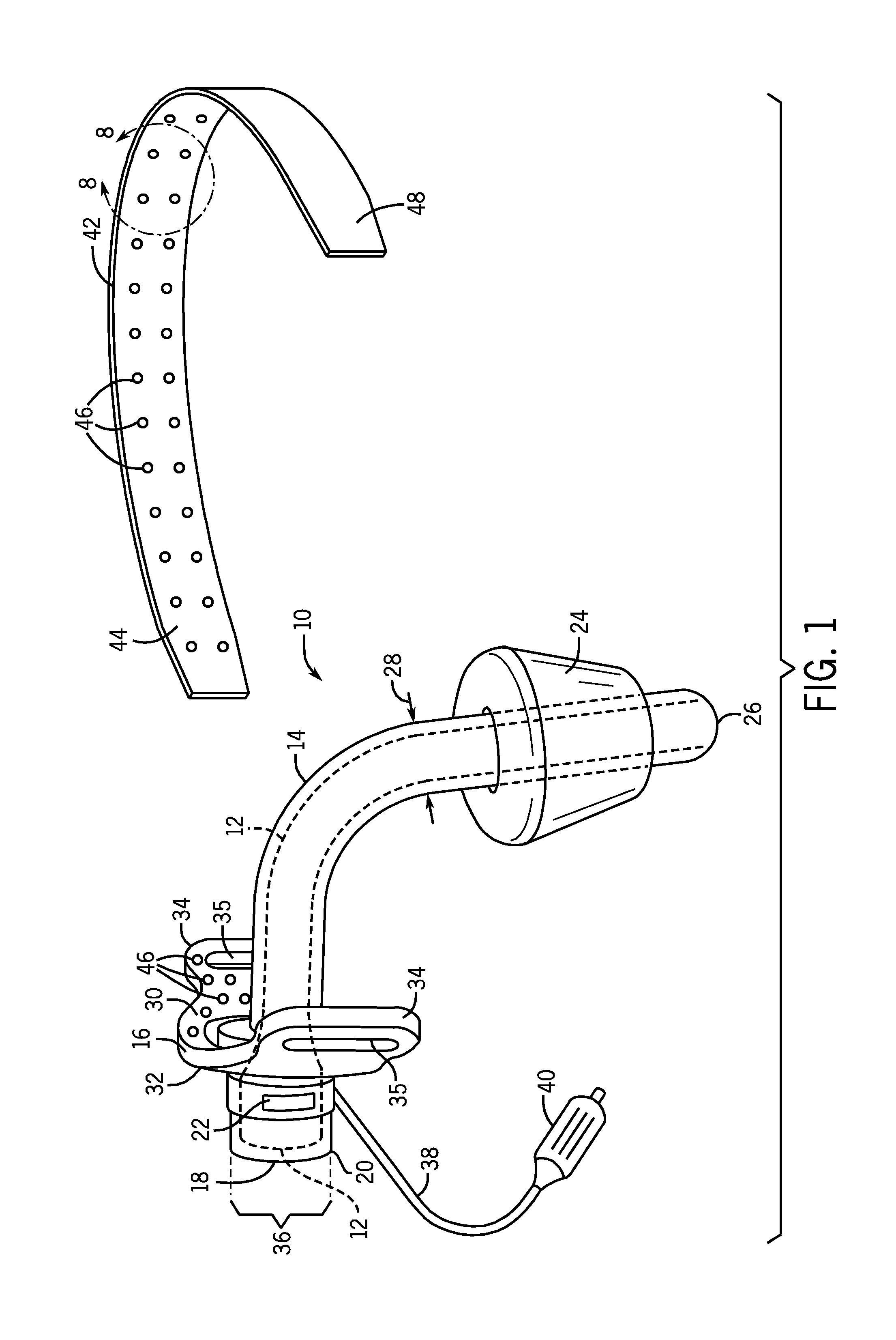
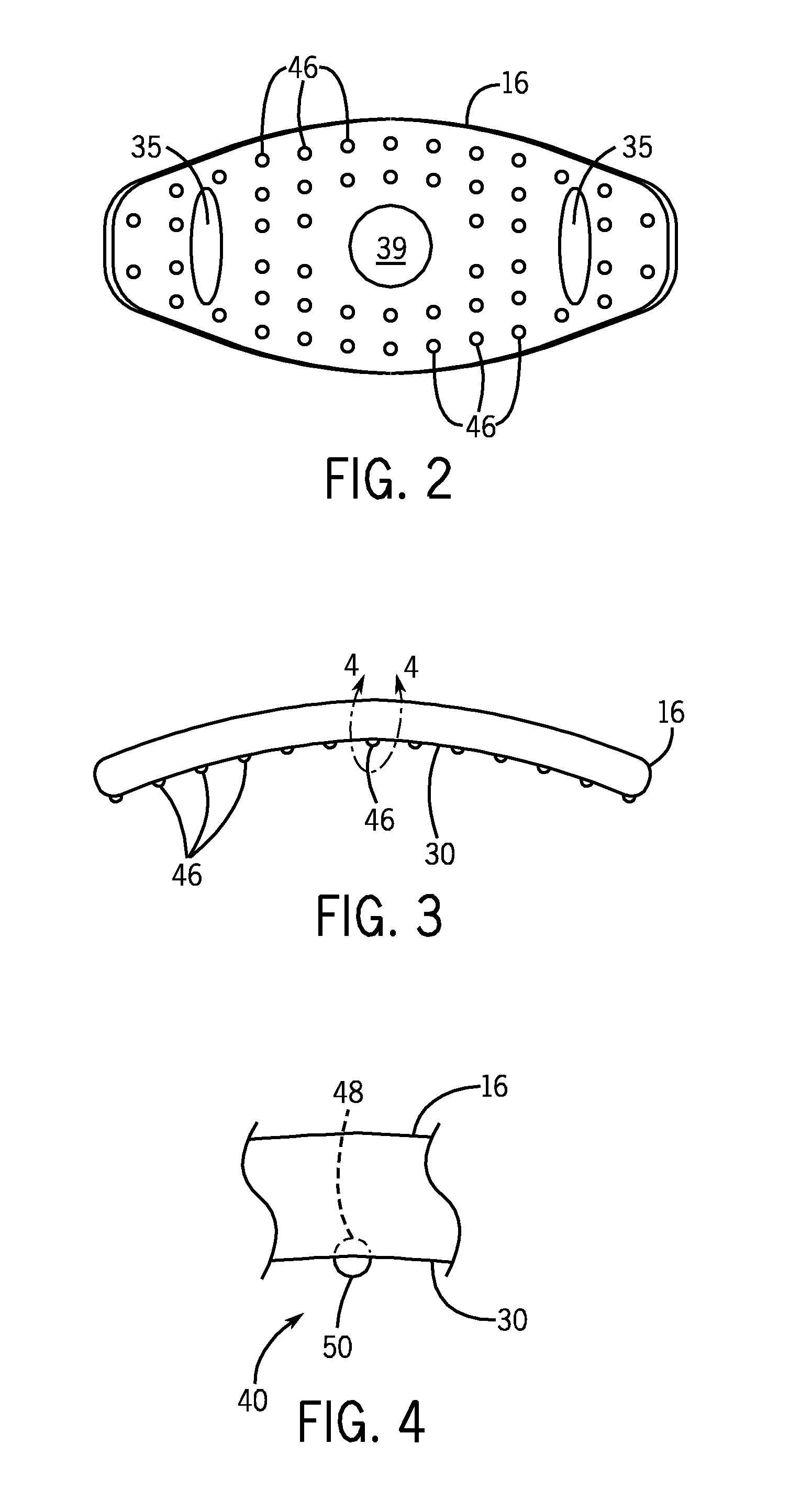
The patent text describes a new tracheal tube design that addresses patient needs and provides better security and comfort. The tube has flanges with soft protrusions that improve friction and help the tube stay in place on the patient's neck. The protrusions also allow air to flow underneath the tube, providing better comfort and reducing sweat. Additionally, the soft protrusions can be added to the strap used to attach the tube to the patient's neck, further enhancing the comfort and wear-ability of the tracheal tube assembly.

Problems solved by technology

One difficulty that arises in the use of tracheal tubes, and tracheostomy tubes in particular, is in securing the tracheostomy tube more comfortably to the patient particularly during long term use.
This may lead to difficulties of the tracheostomy tube becoming decoupled from the patient neck or difficulties in patient comfort.
Additionally the design of typical tracheal tubes may not be as comfortable as desired.

Method used


Image

  • Tracheal tube system for enhanced patient comfort
  • Tracheal tube system for enhanced patient comfort
  • Tracheal tube system for enhanced patient comfort

Examples


Embodiment Construction

[0024]One or more specific embodiments of the present techniques will be described below. In an effort to provide a concise description of these embodiments, not all features of an actual implementation are described in the specification. It should be appreciated that in the development of any such actual implementation, as in any engineering or design project, numerous implementation-specific decisions must be made to achieve the developers' specific goals, such as compliance with system-related and business-related constraints, which may vary from one implementation to another. Moreover, it should be appreciated that such a development effort might be complex and time consuming, but would nevertheless be a routine undertaking of design, fabrication, and manufacture for those of ordinary skill having the benefit of this disclosure.

[0025]A tracheal tube according to a preferred embodiment is illustrated in FIG. 1. While, the tracheal tube system 10 represented in the figures is a tr...


PUM

PropertyMeasurementUnit
Heightaaaaaaaaaa
Heightaaaaaaaaaa
Distanceaaaaaaaaaa

Abstract

A tracheal tube system includes a tracheal tube assembly having a cannula configured to be positioned in a patient airway, and a connector coupled to the proximal end of the cannula. The tracheal tube assembly further includes a flange member secured about the cannula. The flange member includes an interior face configured to be disposed onto a patient neck when in use and a first plurality of protrusions disposed on top of the interior face, wherein the cannula and the connector form a contiguous passageway for exchanging fluid with the patient airway in operation.

Description

BACKGROUND[0001]The present disclosure relates generally to the field of tracheal tubes and, more particularly, to a tracheal tube assembly that enhances patient comfort.[0002]This section is intended to introduce the reader to various aspects of art that may be related to various aspects of the present disclosure, which are described and / or claimed below. This discussion is believed to be helpful in providing the reader with background information to facilitate a better understanding of the various aspects of the present disclosure. Accordingly, it should be understood that these statements are to be read in this light, and not as admissions of prior art.[0003]A wide variety of situations exist in which artificial ventilation of a patient may be desired. For short-term ventilation or during certain surgical procedures, endotracheal tubes may be inserted through the mouth to provide oxygen and other gasses to a patient. For certain applications, particularly when longer-term intubat...

Claims


Application Information

Patent Timeline
IPC IPC(8): A61M16/04A61M16/00
CPCA61M16/0497A61M16/0434A61M16/0057A61M16/0465Y10T29/49826
Inventor SETHIYA, KAMLESHBOLGER, EMMET
Owner TYCO HEALTHCARE GRP LP
Learn More