
Camming dog

a technology of camming dog and locking device, which is applied in the direction of mechanical equipment, transportation and packaging, and mechanical equipment, etc., can solve the problems of screw dog unusability, screw dog is expensive to manufacture and use, and the operator has to exert a considerable amount of effort to rotate the lever dog, etc., to achieve the effect of small and compa

Inactive Publication Date: 2014-07-17
POMPANETTE
View PDF0 Cites 4 Cited by
  • Summary
  • Abstract
  • Description
  • Claims
  • Application Information

AI Technical Summary

Benefits of technology

The invention is a locking mechanism for a portlight. Its technical effects include a fast acting locking dog that is secure, self-parking, and will not accidentally vibrate open, as well as a one-handed operation feature to avoid compressing the gasket. The locking mechanism is also small and compact to prevent injury, and includes a self-parking position when disengaged to eliminate the need for levers and swing bolts.

Problems solved by technology

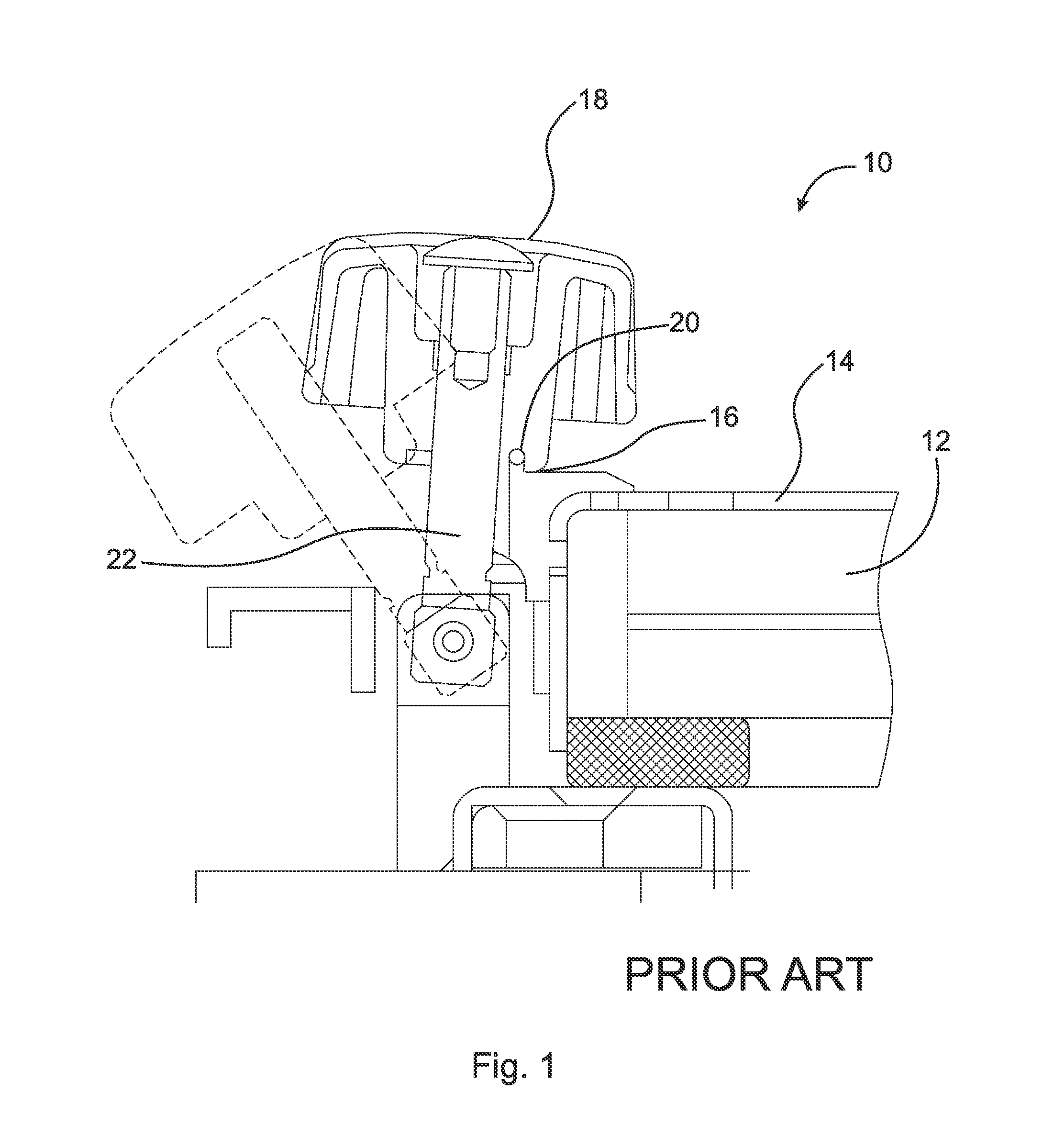
However, rotating lever dogs require the operator to exert a considerable amount of effort, i.e., force, in order to sufficiently close the portlight.
Moreover, screw dogs are expensive to manufacture and are somewhat awkward to use because after the dog is unscrewed far enough to allow the dog to swing clear of the attachment point, e.g., attachment point 20, the knob and its swing bolt, e.g., swing bolt 22, have to be manually rotated out of the way of the lens.
This renders the screw dog unusable in some circumstances.
The entire assembly then grows in size creating more problems with the amount the dog projects above the surface of the lens and the time to unscrew the dogs.
Screw dogs do not easily fit on the narrow edge of the portlight frame, which is a critical characteristic in many dog designs.
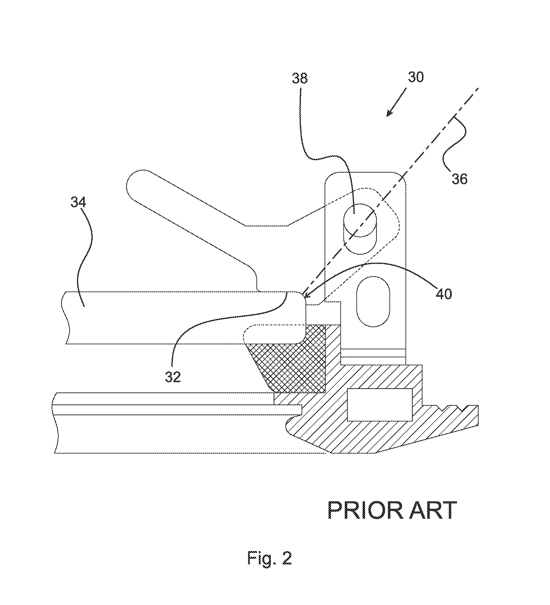
Not only does this arrangement make for a weak dog and a portlight that deflects when dogged down, it also requires a tremendous amount of force to disengage the dog, and therefore imposes pretty tight tolerances on the lens / dog mechanical layout.
The above described prior art designs each have deficiencies with respect to at least one of the foregoing desirable characteristics.

Method used


Image

  • Camming dog
  • Camming dog
  • Camming dog

Examples


Embodiment Construction

[0039]At the outset, it should be appreciated that like drawing numbers on different drawing views identify identical, or functionally similar, structural elements of the invention. While the present invention is described with respect to what is presently considered to be the preferred aspects, it is to be understood that the invention as claimed is not limited to the disclosed aspects.

[0040]Unless defined otherwise, all technical and scientific terms used herein have the same meaning as commonly understood to one of ordinary skill in the art to which these embodiments belong. As used herein, “dog” is intended to be broadly construed as a mechanical device for holding a port, window, lens, hatch or other closing in a closed and secured position.

[0041]Furthermore, it is understood that this invention is not limited to the particular methodology, materials and modifications described and as such may, of course, vary. It is also understood that the terminology used herein is for the p...


PUM


Abstract

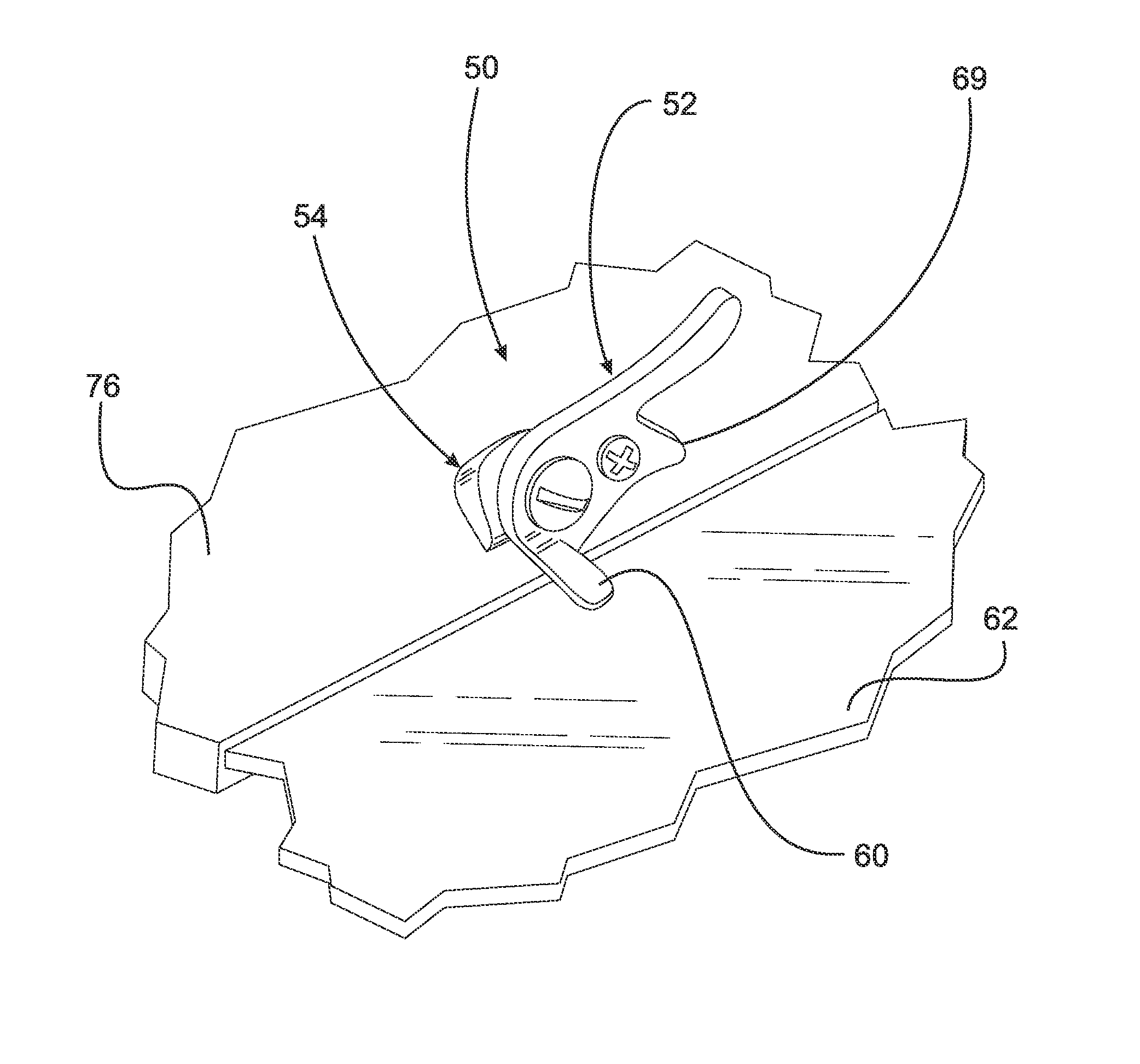
A camming dog configured for use with a window having a frame and a hinged lens. The camming dog includes an angled base having a base mounting portion and a handle mounting portion, wherein the base mounting portion is secured to the frame, the base mounting portion is disposed at an angle relative to the handle mounting portion, the angle is less than ninety degrees. The camming dog further includes a handle having an arm boss, wherein the handle is rotationally secured to the handle mounting portion of the angled base and rotates about an axis of rotation. Upon rotation of the handle to an open position, the hinged lens rotates unimpeded past the arm boss and upon rotation of the handle to a closed position, the hinged lens is secured within the frame by the arm boss.

Description

FIELD OF THE INVENTION[0001]The invention broadly relates to locking devices, more particularly to locking devices used on port assemblies on marine vessels, and even more particularly to a camming dog locking device used on port assemblies on marine vessels.BACKGROUND OF THE INVENTION[0002]Portlights make it possible for fresh air and light to pass into the interior of a marine vessel, thereby creating a more enjoyable environment. A variety of dogging mechanisms used in combination with one or more gaskets have been employed in port assemblies to ensure that the assemblies are sealed from environmental ingress, e.g., water, salt, cold air, etc., when the assemblies are in closed positions.[0003]Rotating lever dogs, such as those shown in U.S. Pat. No. 5,842,433, are rather simple in design. The operator pushes the lens closed and against a gasket with one hand while rotating the lever from a parked position to a locking position. The parked position is typically parallel to the fr...

Claims


Application Information

Patent Timeline
IPC IPC(8): E05C3/14
CPCE05C3/14E05B63/0056E05C3/04B63B2019/0069Y10T292/1041
Inventor KYLE, JAMES H.
Owner POMPANETTE
Learn More