Wireless transmission device and wireless transmission method

a transmission device and wireless transmission technology, applied in the field of wireless transmission devices and wireless transmission methods, can solve the problems of deteriorating precision of reproduction clock frequency and time and extension of reception cycle of timing packets, and achieve the effect of maintaining the accuracy of clock frequency and tim

Inactive Publication Date: 2014-07-17
NEC CORP
View PDF0 Cites 16 Cited by
  • Summary
  • Abstract
  • Description
  • Claims
  • Application Information

AI Technical Summary

Benefits of technology

[0017]According to the present invention, the transition from a timing reproduction mode to a holdover mode is made when a wireless frame error rate is greater than a first threshold value by demodulating a wireless frame from a wireless output signal received from a wireless transmission path and calculating the wireless frame error rate from an error detection code within the demodulated wireless frame. Thereby, a wireless transmission device can maintain precision of a clock frequency and time by detecting an abnormal state shortly after a defect occurs in a device or transmission path without executing EOAM control.

Problems solved by technology

Further, when a signal according to a packet is transmitted via a wireless transmission path, the extension of a reception cycle of a timing packet and the precision deterioration of a reproduction clock frequency and time are problematic according to packet loss due to a signal error intermittently caused by device failure and worsening weather.

Method used


Image

  • Wireless transmission device and wireless transmission method
  • Wireless transmission device and wireless transmission method
  • Wireless transmission device and wireless transmission method

Examples


first embodiment

[0023]The first embodiment of the present invention will be described in detail with reference to the drawings.

[0024]In the first embodiment of the present invention, in a wireless transmission device which reproduces a clock frequency and time by receiving a timing packet of IEEE 1588 Precision Time Protocol (hereinafter referred to as “IEEE 1588 PTP”) the wireless transmission device makes a normal determination on each of wireless and packet transmission paths in addition to a normal determination on a timing packet. Thereby, the wireless transmission device can transition to the holdover mode shortly after the occurrence of a defect in a device or a transmission path, and hold precision of a clock frequency and time.

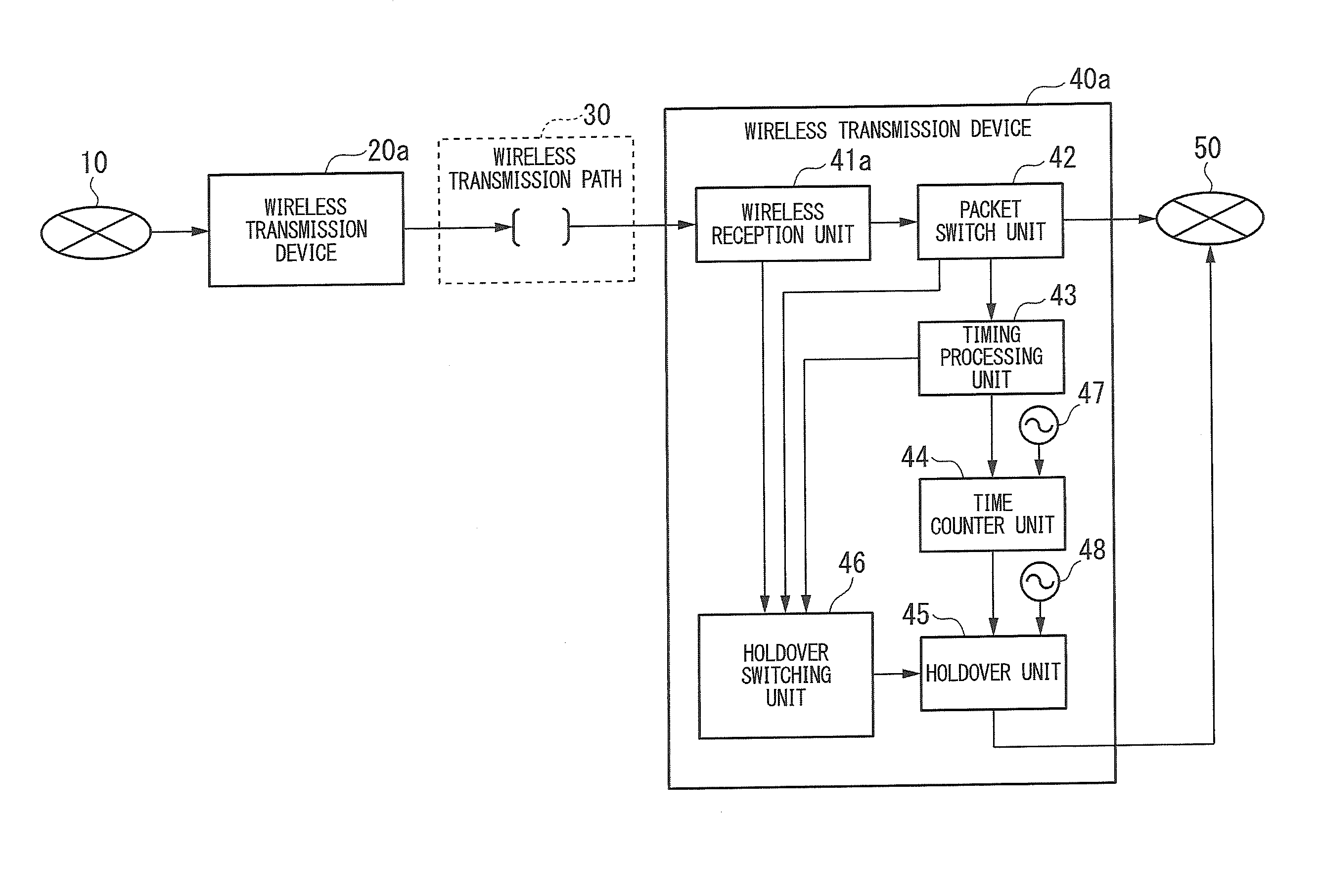
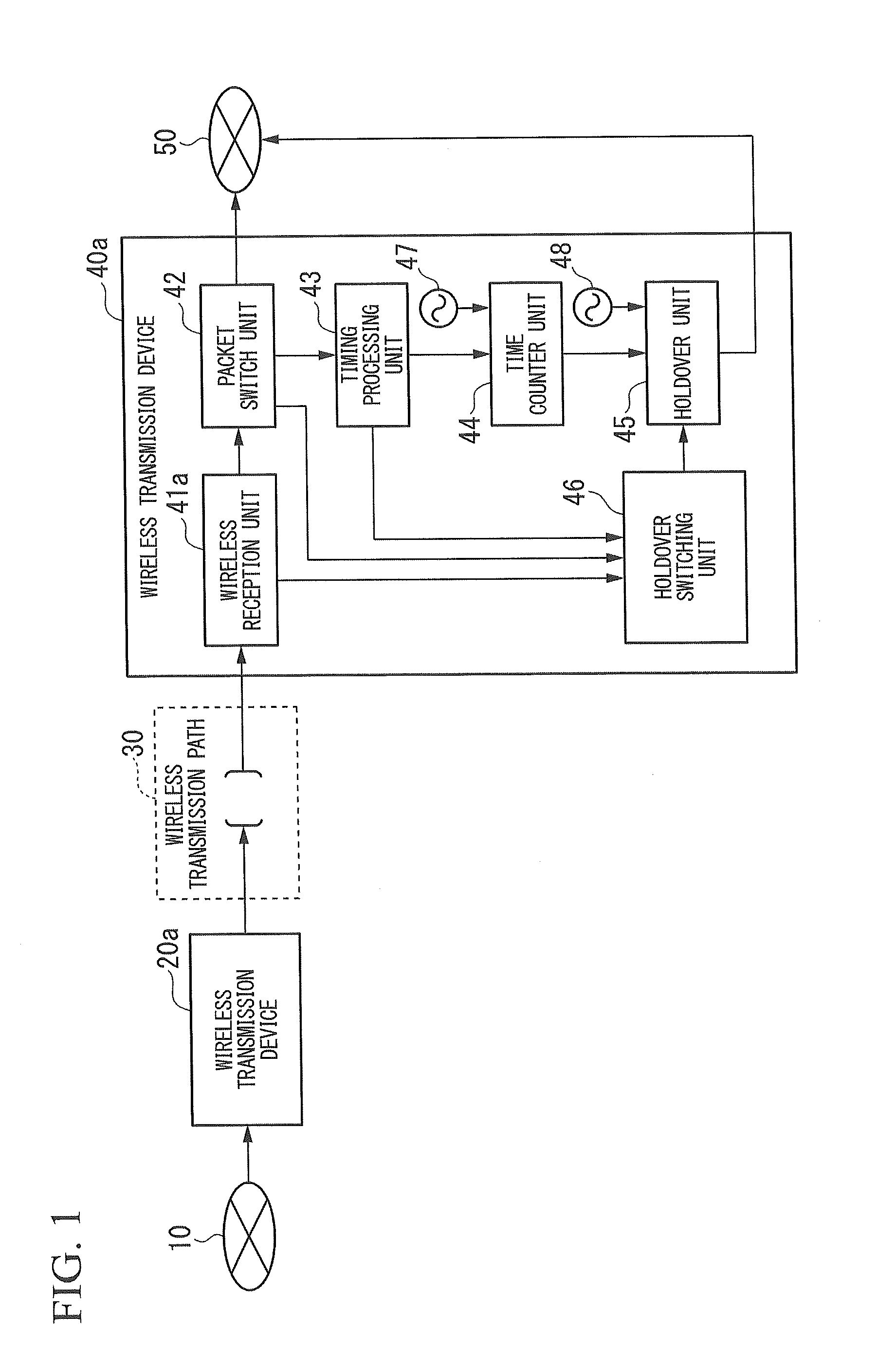
[0025]FIG. 1 is a block diagram illustrating a configuration of a system having the wireless transmission device. Within a user network 10, a transmission device (not illustrated) to be used by a user and a master station (not illustrated) serving as a synchronizatio...

second embodiment

[0064]The second embodiment of the present invention will be described in detail with reference to the drawings.

[0065]The second embodiment is different from the first embodiment in that an adaptive modulation scheme is adopted in the wireless transmission device and a holdover transition condition is designed. Hereinafter, only differences from the first embodiment will be described.

[0066]FIG. 4 is a block diagram illustrating a configuration of a system having a wireless transmission device. The wireless transmission devices 20b and 40b are wireless transmission devices in which the adaptive modulation scheme is adopted.

[0067]Here, the adaptive modulation scheme is a scheme of maximizing an executable band according to wireless reception power and performing switching to a modulation scheme robust against disturbance according to power and noise when reception power is decreased due to weather worsening or the like. A predetermined algorithm may be appropriately used in the adapti...


PUM


Abstract

A wireless transmission device includes a wireless reception unit which receives and demodulates a wireless frame in which a local area network (LAN) signal including a timing packet and an error detection code are multiplexed and converted into a high-frequency wireless output signal from a wireless transmission path, separates the LAN signal from the demodulated wireless frame, and calculates a wireless frame error rate by detecting a signal error of the wireless frame from the error detection code within the wireless frame, and a holdover switching unit which switches an operation mode from a timing reproduction mode in which a clock and a timing pulse are output based on a cycle and a phase reproduced from a timing packet included in the LAN signal to a holdover mode in which a clock and a timing pulse are output based on a cycle and a phase saved at a normal time when the wireless frame error rate calculated by the wireless reception unit is greater than a first threshold value.

Description

TECHNICAL FIELD[0001]The present invention relates to a wireless transmission device and a wireless transmission method.BACKGROUND ART[0002]In a wireless transmission device having a function of reproducing a clock frequency and time by receiving a timing packet of IEEE 1588 Precision Time Protocol (Non-Patent Document 1), it is necessary to prevent the extension of a correction cycle and the deterioration of synchronization precision of a clock frequency and time when timing packet loss occurs due to a signal error in wireless and packet transmission paths. Because of this, when a defect occurs in a device or a transmission path and therefore the reception of a timing packet is impossible or the extension of a reception cycle occurs, the wireless transmission device is configured to put a speed of clock frequency and time deviations from a master station serving as a synchronization information source within a predetermined value by performing switching from a timing reproduction m...

Claims


Application Information

Patent Timeline
Patent Type & Authority Applications(United States)
IPC IPC(8): H04W56/00
CPCH04W56/005H04J3/0641H04J3/0667H04W56/0035H04L1/0003H04L1/203
Inventor NAKAJIMA, HIROAKI
Owner NEC CORP
Why Eureka
Try Eureka