Automatic gain control and wireless communication device

a gain control and wireless communication technology, applied in transmission monitoring, power management, phase-modulated carrier systems, etc., can solve problems such as the reduction of the precision of the conversion by the analog-to-digital converter

Inactive Publication Date: 2006-06-20
MITSUBISHI ELECTRIC CORP
View PDF20 Cites 17 Cited by
  • Summary
  • Abstract
  • Description
  • Claims
  • Application Information

AI Technical Summary

Benefits of technology

[0005]An object of the present invention is to provide an automatic gain controller and a wireless base station in which a precision in conversion by an analog-to-digital converter is maintained at a proper level even when an environment for reception is changed.

Problems solved by technology

For this reason, a signal not adapted for the dynamic range of the analog-to-digital converter may be input to the analog-to-digital converter when there is a rapid change in the level of received power, resulting in decrease in the precision in conversion by the analog-to-digital converter.

Method used


Image

  • Automatic gain control and wireless communication device
  • Automatic gain control and wireless communication device
  • Automatic gain control and wireless communication device

Examples


first embodiment

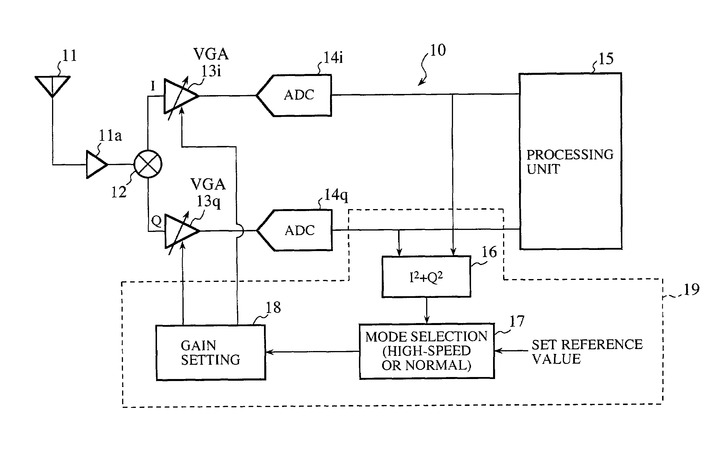
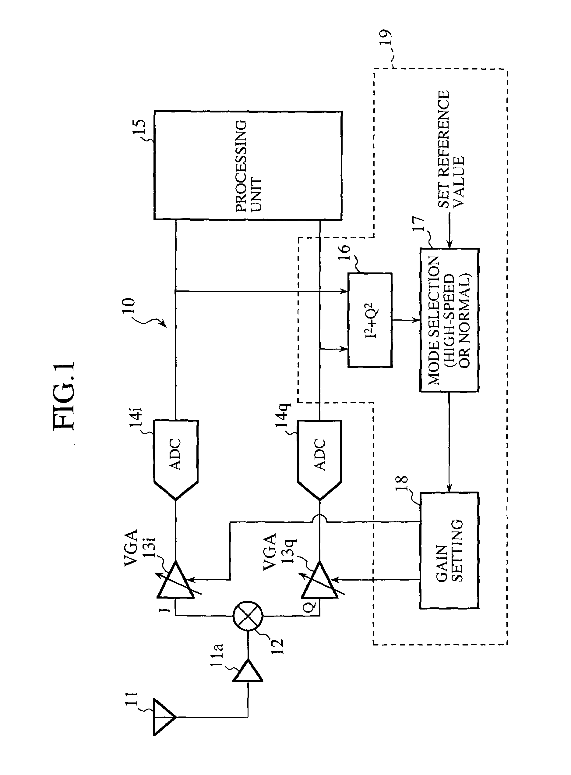
[0052]FIG. 1 is a block diagram showing an electrical construction of a wireless communication apparatus according to a first embodiment of the present invention. The wireless communication apparatus 10 comprises an antenna 11a, a mixer 12, variable gain amplifiers (VGA) 13i and 13q, analog-to-digital converters 14i and 14q, a processing unit 15, and an automatic gain controller (AGC) 19.

[0053]The antenna 11 receives a radio signal from a wireless terminal such as a portable terminal. The wireless terminal is configured to generate a radio signal by mixing an I component and a Q component by quadrature modulation. The mixer 12 detects the signal from the antenna 11 so as to retrieve the I component and the Q component by a process of isolation. The variable gain amplifiers 13i and 13q respectively amplify the I component and the Q component isolated by the mixer 12. The analog-to-digital converters 14i and 14q convert the analog signals received from the variable gain amplifiers 13i...

second embodiment

[0078]FIG. 7 is a block diagram showing an electrical construction of a wireless communication apparatus according to a second embodiment of the present invention. The wireless communication apparatus 20, which is a variation of the wireless communication apparatus of the first embodiment, comprises an antenna 21, an amplifier 21a, a mixer 22, variable gain amplifiers (VGA) 23i and 23q, analog-to-digital converters 24i and 24q, a processing unit 25, and an automatic gain controller (AGC) 29. The antenna 21, the amplifier 21a, the mixer 22, the variable gain amplifiers (VGA) 23i and 23q, the analog-to-digital converters 24i and 24q, and the processing unit 25 are the same as the corresponding components of FIG. 1 so that the description thereof is omitted.

[0079]The automatic gain controller 29 is provided with an operation unit (I2) 26i, an operation unit (Q2) 26q, mode selection units 27i and 27q, and gain setting units 28i and 28q so as to control the gain of the variable amplifier...

third embodiment

[0082]FIG. 8 is a block diagram showing an electrical construction of a wireless communication apparatus according to a third embodiment of the present invention. The wireless communication apparatus 30, a variation of the wireless communication apparatus of the first embodiment, comprises antennas 31 and 41, the amplifiers 31a and 41a, mixers 32 and 42, variable gain amplifiers (VGA) 33i, 33q, 43i, 43q, analog-to-digital converters 34i, 34q, 44i, 44q, a processing unit 35, and an automatic gain controller (AGC) 49.

[0083]The antennas 31, the amplifier 31a, the mixer 32, the variable gain amplifiers (VGA) 33i and 33q, and the analog-to-digital converters 34i and 34q constitute a first branch for diversity reception. These components are the same as the corresponding components of FIG. 1 so that the description thereof is omitted. The antenna 41, the amplifier 41a, the mixer 42, the variable gain amplifiers (VGA) 43i and 43q, and the analog-to-digital converters 44i and 44q constitute...


PUM


Abstract

A wireless communication apparatus includes an antenna receiving a radio signal, a variable gain amplifier amplifying the received signal using a variable gain, an analog-to-digital converter converting the amplified signal into a digital signal, a gain setting unit periodically updating the gain of the variable gain amplifier in accordance with an output from the analog-to-digital converter, and an operating mode selection unit selecting one of a plurality of operating modes characterized by different gain updating periods in accordance with the output from the analog-to-digital converter, the selected operating mode being set in the gain setting unit. With this construction, the precision in conversion by the analog-to-digital converter is maintained at a proper level when an environment for signal reception varies.

Description

TECHNICAL FIELD[0001]The present invention relates to an automatic gain controller controlling a gain of a variable gain amplifier provided at an input of an analog-to-digital converter, and also to a wireless communication apparatus using the same.BACKGROUND ART[0002]FIG. 9 shows a wireless communication apparatus to which an automatic gain controller (AGC) according to the related art is applied. In the wireless communication apparatus, a signal received by an antenna 2 is amplified by an amplified 3 and a variable gain amplifier 4. An I-component and a Q-component of the amplified signal are isolated by a mixer 5. The isolated signals are then subject to analog-to-digital conversion by analog-to-digital converters 6i and 6q, respectively and are decoded by a processing unit 7. An automatic gain controller 8 calculates a difference between an output value of the analog-to-digital converter 6i and a reference value and also calculates a difference between an output value of the ana...

Claims


Application Information

Patent Timeline
Patent Type & Authority Patents(United States)
IPC IPC(8): H04L27/06H03G3/30H03M1/18H04B1/30H04B7/005H04L27/22H04L27/38
CPCH03G3/3036H03G3/3052H03M1/185H04W52/52H04L27/22H04L27/38H04L27/3809H04B1/30
Inventor SAKIMA, NOBUHIRO
Owner MITSUBISHI ELECTRIC CORP
Why Eureka
Try Eureka