
Tooling base

a tooling base and base technology, applied in the field of tooling bases, can solve the problems of complicated internal design of the known tooling bases, especially the mechanism, the base, and the difficulty of manufactur

Active Publication Date: 2018-02-27
5TH AXIS INC
View PDF9 Cites 15 Cited by
  • Summary
  • Abstract
  • Description
  • Claims
  • Application Information

AI Technical Summary

Benefits of technology

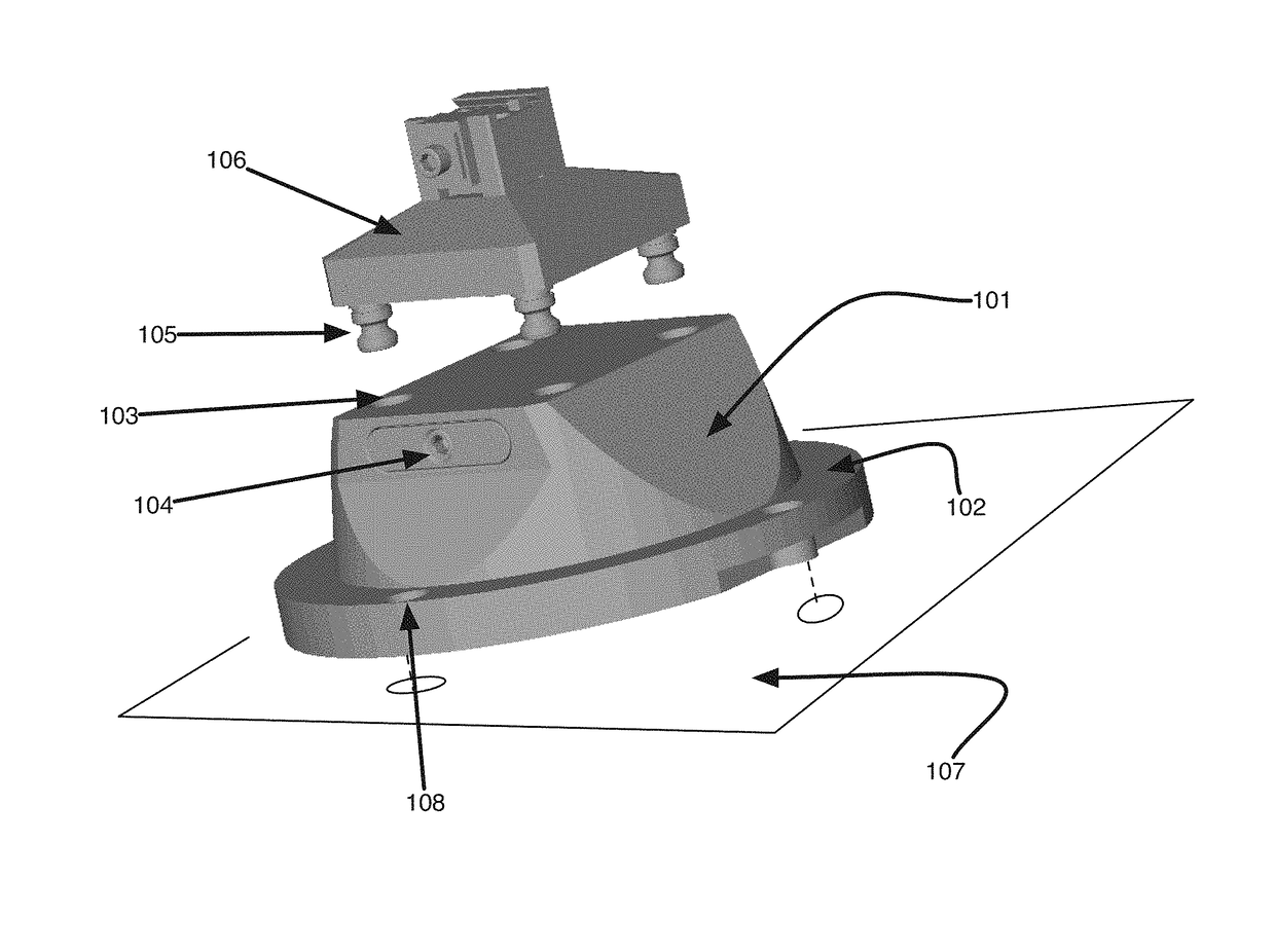
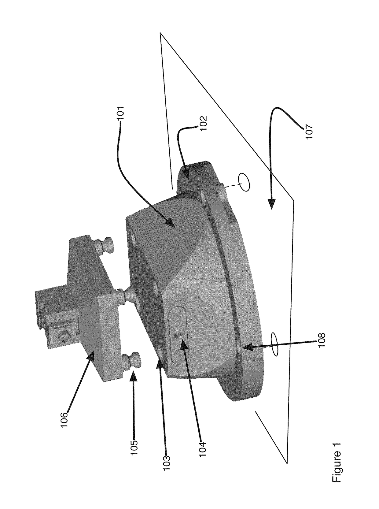
The tooling base is a new design that simplifies parts and makes manufacturing easier. It uses clamps on threaded rods that are limited in movement within the base. This allows for easier design and manufacture of parts while maintaining precise and accurate alignment between the tooling fixture and the base.

Problems solved by technology

However, the internal design of the known tooling bases, especially the mechanism that is used to clamp and release the tooling fixture to the base, are complicated and difficult to manufacture.

Method used


Image

  • Tooling base
  • Tooling base
  • Tooling base

Examples


second embodiment

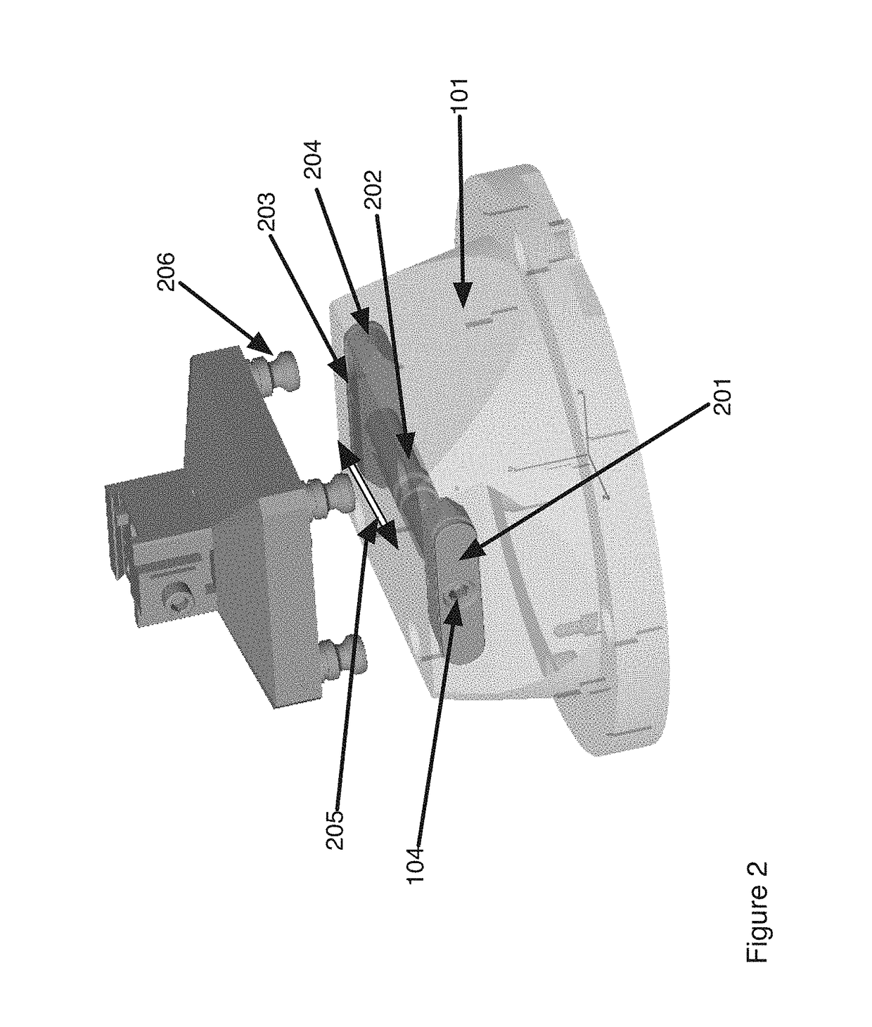
[0023]FIG. 6 shows the internal components of the tooling base. The components include clamping fixtures 607 that are fitted to a threaded shaft 601 through threaded holes 602. The threads on the shaft 603, 605 include left hand and right hand threads such that rotation of the shaft causes the clamping fixture to move towards and away from one another. In this embodiment each end 609 of the clamping fixtures are tapered to engage an indentation on the alignment studs 610 thereby clamping the alignment studs in place when the shaft is rotated to bring the clamping fixtures towards one another. The tooling base further includes a stop. The stop is comprised of a pair of ridges 604 incorporated on the shaft and cylindrical posts 608 that fit between the ridges and thereby restrict the movement of the combined assembly of the alignment fixtures and the shaft to the width of the region between the ridges 604. Note that in this embodiment and the previous one movement of the alignment fix...

third embodiment

[0024]the tooling base is shown in FIG. 7. The tooling base 701 is comprised of a base that is registered and clamped to a milling or other processing machine as is known in the art and the base includes tooling holes 702 into which are fitted alignment studs 703. This embodiment includes at least one threaded shaft (two are shown in the example) that when rotated causes clamping fixtures (best seen in FIG. 8) to engage the alignment studs and clamp the studs in place in the tooling hole 702 of the base. The tooling base further includes a stop that is comprised of at least one post 705 that is threaded into the tooling base 701 and extends into the interior and fits within a pair of ridges on the threaded rod(s) 704.

[0025]FIG. 8 shows details of interior components of the tooling base of FIG. 7. The tooling base is comprised of at least one threaded shaft 801, 802 (here two are shown) that include threaded regions 803. Clamping fixtures 804 include threaded holes (not labeled) and ...


PUM


Abstract

A tooling base that is an improvement over current designs in the form of simplified number of parts and easier manufacturing of parts is described. The tooling base uses alignment fixtures on threaded rods that are restricted in their movement within the tooling base by stops. The stops are located either on the threaded shafts or on the alignment fixtures. This allowed degree of movement enables simplified part design and manufacture while maintaining the precision and accuracy of registration of a tooling fixture with the tooling base.

Description

CROSS-REFERENCE TO RELATED APPLICATIONS[0001]Not Applicable.STATEMENT REGARDING FEDERALLY SPONSORED RESEARCH OR DEVELOPMENT[0002]Not Applicable.BACKGROUND OF THE INVENTIONTechnical Field[0003]The present invention relates to a tooling base that is used to attach a variety of tooling fixtures that would hold a workpiece to a work surface for machining. The base allows the fixtures and workpieces to be removed and re-attached while maintain registration accuracy.Related Background Art[0004]A tooling fixture is used to hold a workpiece during intricate machining such as 5 axis machining. The fixture system requires that the workpiece be held securely and precisely and provides access to a machine tool to all facets of the workpiece. Preferably it is possible to prepare the raw stock and easily and removably mount the stock in the fixture to present to a machine to create a part. Often Tooling fixtures are mounted directly to the bed or work surface of the milling machine. However, in m...

Claims


Application Information

Patent Timeline
IPC IPC(8): B25B1/02B23Q3/10B23Q3/18B25B1/24F16B2/12
CPCB23Q3/102B23Q3/186F16B2/12B25B1/24B23Q1/0072
Inventor TAYLOR, CHRISGRANGETTO, STEVELANE, ADAM
Owner 5TH AXIS INC
Learn More