
Deviation detection in mobile transit systems

a technology for mobile transit and detection of deviations, applied in surveying and navigation, instruments, navigation instruments, etc., can solve problems such as delays, deviating from schedules, and transit vehicles delaying buses,

Active Publication Date: 2014-07-17
HERE GLOBAL BV
View PDF2 Cites 34 Cited by
  • Summary
  • Abstract
  • Description
  • Claims
  • Application Information

AI Technical Summary

Benefits of technology

The patent describes a way for a mobile device or network device to track when a bus is running off schedule. Based on the device's location and the information about the path it's following, the device calculates a target route for the bus to follow. As the bus travels, it compares this target route to the device's location. If there's a deviation, the device sends a message to the bus driver or recommends a new route. The technology helps ensure the bus runs on time and helps people get to their destinations more efficiently.

Problems solved by technology

In the example of train routes, track construction, or accident may cause the train to use a different line of tracks.
Transit vehicles may also deviate from schedules because of delays arising from route deviations or re-routes.
However, several events can disrupt the schedule.
In the example of bus routes, an accident or congestion can cause traffic, which delays the buses.
In addition, when many riders have congregated at a stop, the bus is delayed as riders enter the bus and scan their fare cards.
In the example of train routes, heavy usage or interference by other trains causes delays for riders to board and disembark.
These usage types of delays tend to snowball.
Fewer riders are at the stop when the next bus arrives, which causes the next bus to spend less time at the spot and tend to catch up with the first bus.
Both temporal and spatial deviations of transit vehicles impair the ability of users to predict when the transit vehicle will arrive at a stop or station and / or locate the new location of the stop or station.
Tall buildings may partially block GPS signals.
Additionally, the illustrations are merely representational and may not be drawn to scale.

Method used


Image

  • Deviation detection in mobile transit systems
  • Deviation detection in mobile transit systems
  • Deviation detection in mobile transit systems

Examples


Embodiment Construction

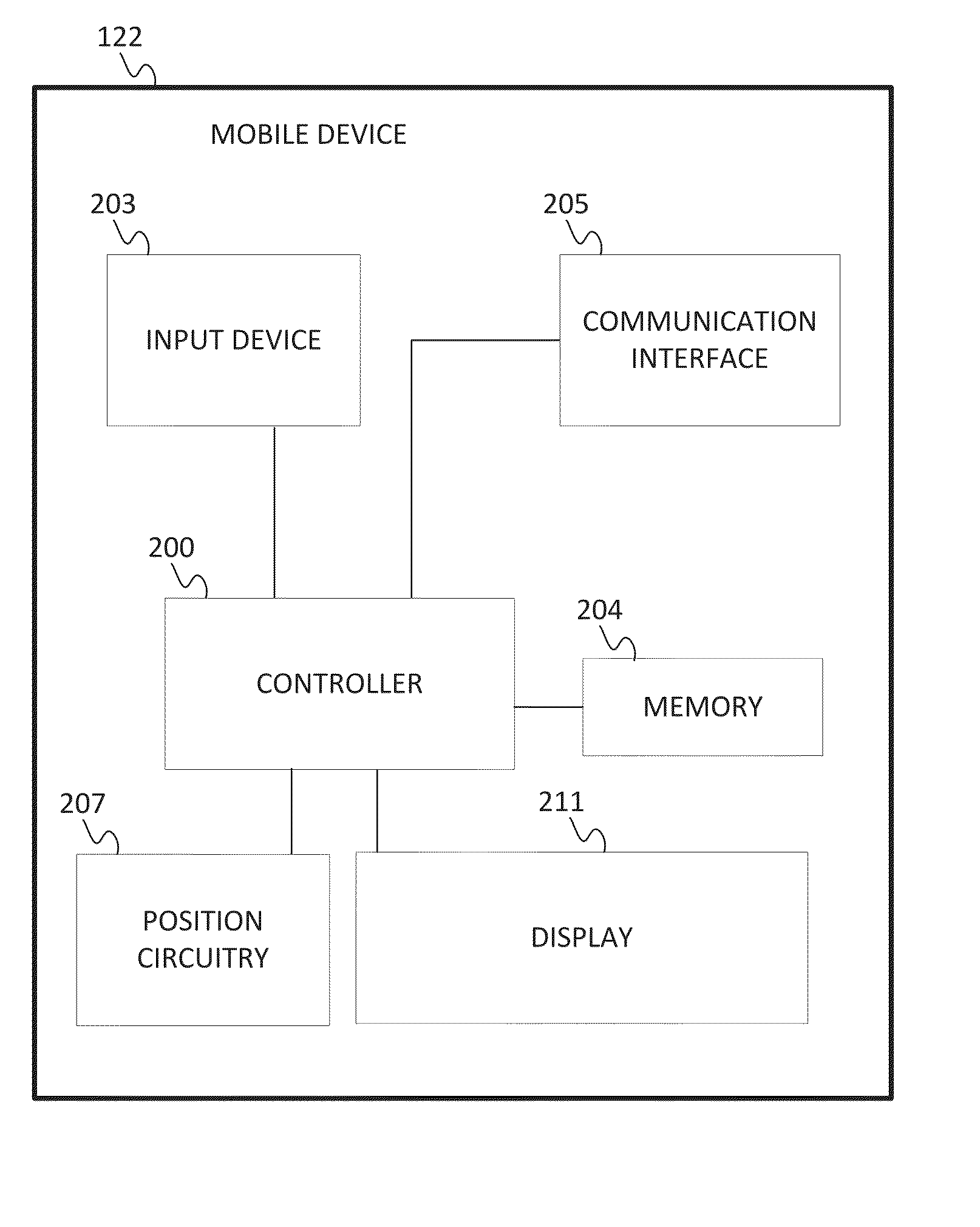
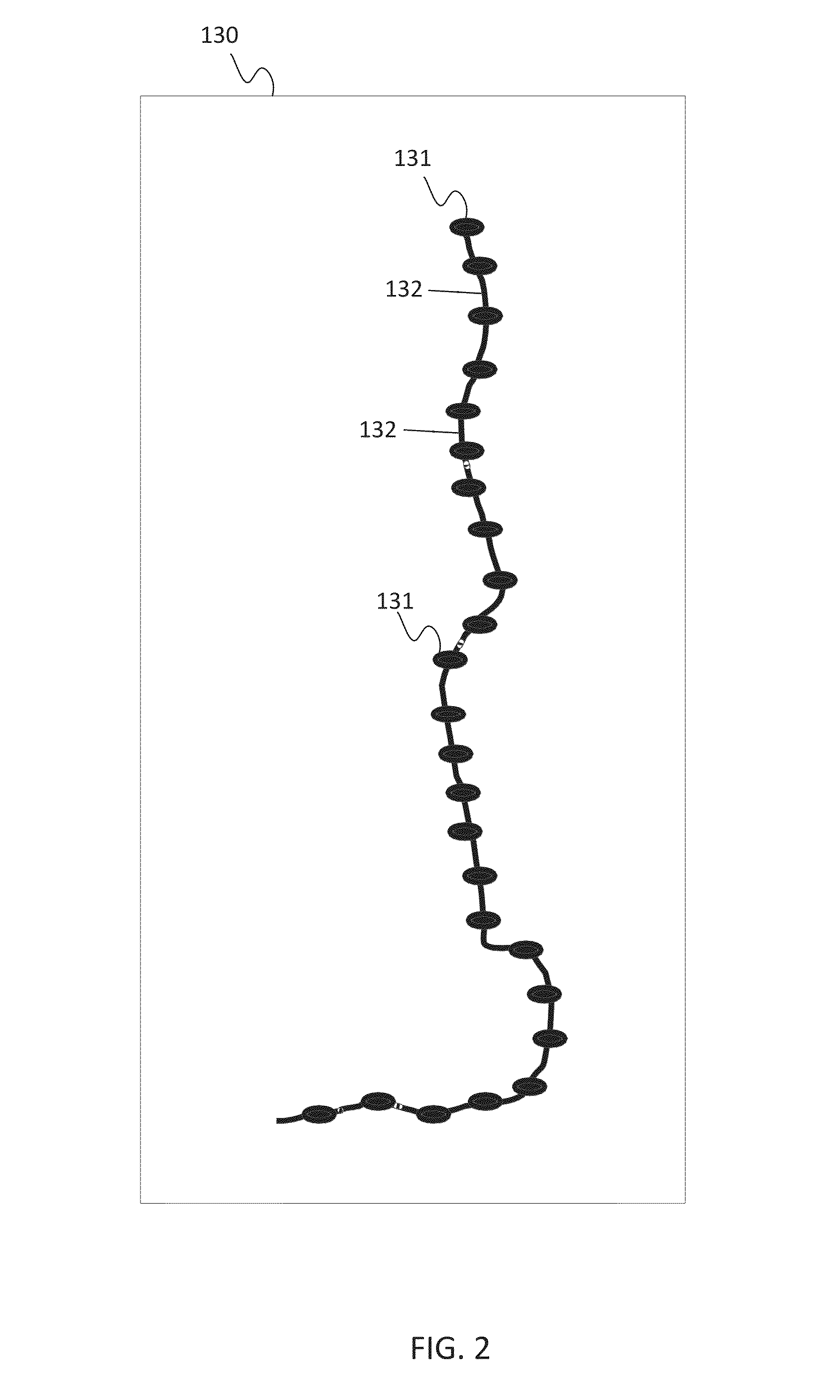
[0017]The following embodiments include the detection in real time of when and where a mobile transit object deviates from a scheduled route or a historical route. The scheduled route may be a series of estimated times paired with geographic locations for transit stops or stations. The historical route may be an average of recorded times and / or geographic locations from past routes on the transit system. The deviation may be either spatial or temporal. Once the deviation is identified, the deviation may be utilized to choose a new route or derive the new route for display to users. In addition, the deviating location points may be used to construct a new route leg, a new stop, and / or new schedules for the transit system. The new information may be transmitted to users or the transit system administrator.

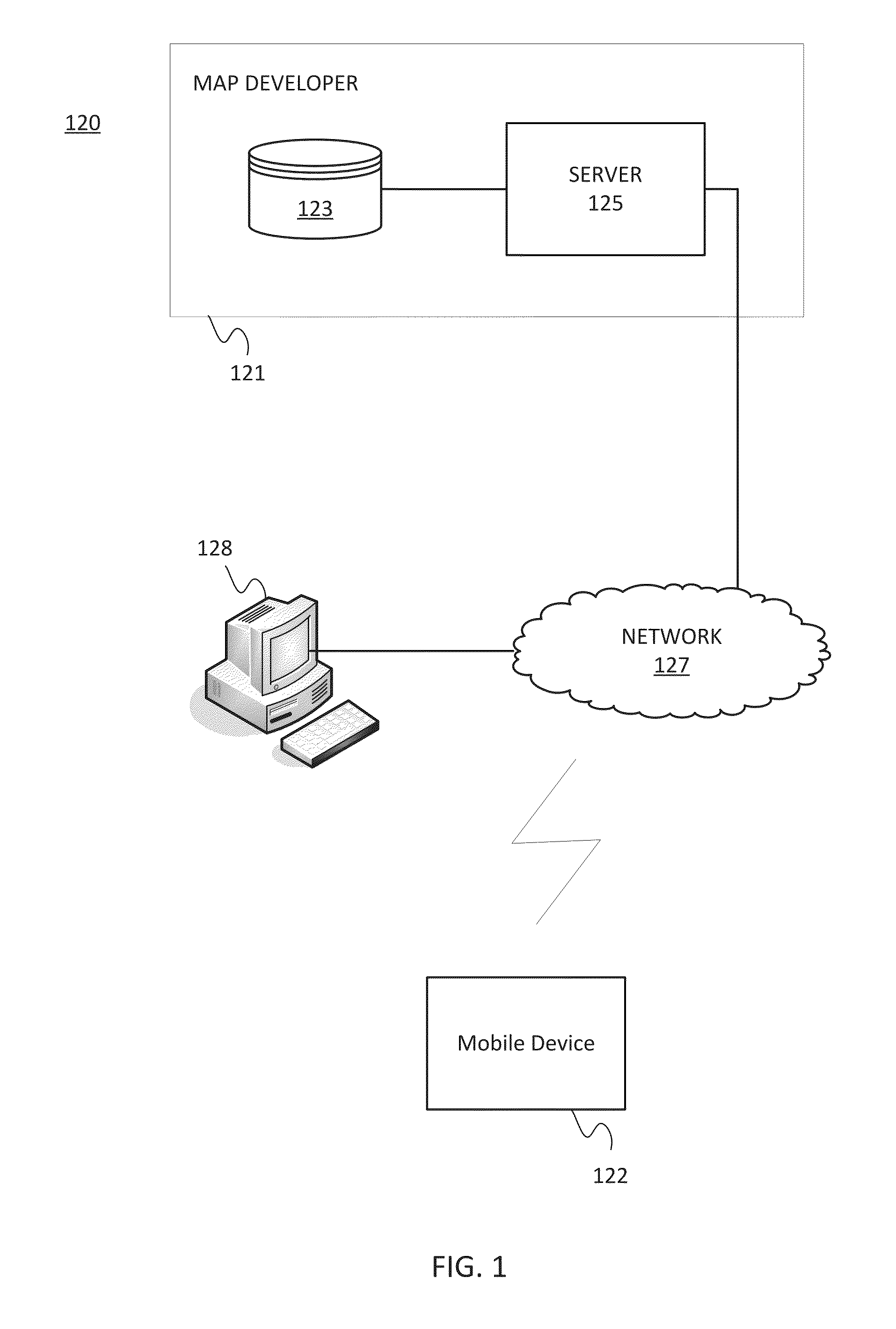
[0018]FIG. 1 illustrates an exemplary navigation system 120 for route deviation detection. The navigation system 120 includes a map developer system 121, a mobile device 122, a works...


PUM


Abstract

In one embodiment, a mobile device or a network device is configured to identify when a transit vehicle deviates from a transit path. The mobile device is configured to perform a positioning technique to generate data indicative of the location of a mobile device. Based on the location of the mobile device, a path is identified. The path is associated with an estimated path width based on the classification of the path and / or the accuracy of the positioning technique. A target route is calculated using the estimated path width. As the transit vehicle travels, the target route is compared to the location of the mobile device. If the mobile device and or transit vehicle deviates from the target route, a message is generated. The message may indicate that the transit vehicle is being re-routed and / or recommends the computation of a new path.

Description

FIELD[0001]The following disclosure relates to location tracking in transportation systems.BACKGROUND[0002]Transportation systems include automobiles, buses, trains, and other modes of transportation. Example transportation systems include the public transit systems of many metropolitan areas. In a transit system, the transit vehicle typically follows a set route. The route is a path from station to station or from stop to stop.[0003]Occasionally, transit vehicles do not follow the scheduled routes. In the example of bus routes, a bus may be re-routed because of a traffic incident (e.g., an accident or congestion), a flood, an event (e.g., a parade or motorcade), or a variety of reasons. In the example of train routes, track construction, or accident may cause the train to use a different line of tracks. Sometimes the re-routing is scheduled and sometimes the re-routing occurs without warning.[0004]Transit vehicles may also deviate from schedules because of delays arising from route...

Claims


Application Information

Patent Timeline
Patent Type & Authority Applications(United States)
IPC IPC(8): G01C21/20
CPCG01C21/20G01C21/30G01S19/48G01S19/22G01C21/34
Inventor MODICA, LEOSTENNETH, LEON
Owner HERE GLOBAL BV
Learn More