Apparatus and Methods Thereof for Error Correction in Split Core Current Transformers

a split core current transformer and error correction technology, applied in the field of power consumption measurement, can solve the problems of deficiency of power meters, deficient use of such devices, etc., for the purpose of measuring relatively low currents in the environment of a plurality of circuit breakers, and unable to meet the requirements of measurement. , to achieve the effect of reducing the number of circuit breakers, and improving the accuracy

Active Publication Date: 2014-07-17
PANORAMIC POWER
View PDF8 Cites 41 Cited by
  • Summary
  • Abstract
  • Description
  • Claims
  • Application Information

AI Technical Summary

Problems solved by technology

Using such devices, or power meters for that matter, is deficient for the purposes of measuring relatively low currents in an environment of a plurality of circuit breakers.
Providing wireless telemetry on a singular basis, such as suggested by Gunn et al., and other prior art solutions, suffers from deficiencies when operating in a noisy environment.
A major problem with split core CT's is that the measurement result is highly sensitive to the air-gap that always exists between the two parts of the core.
As a result, such CT's cannot be practically used in applications requiring a high level of accuracy, such as, for exampl...

Method used


Image

  • Apparatus and Methods Thereof for Error Correction in Split Core Current Transformers
  • Apparatus and Methods Thereof for Error Correction in Split Core Current Transformers
  • Apparatus and Methods Thereof for Error Correction in Split Core Current Transformers

Examples


Embodiment Construction

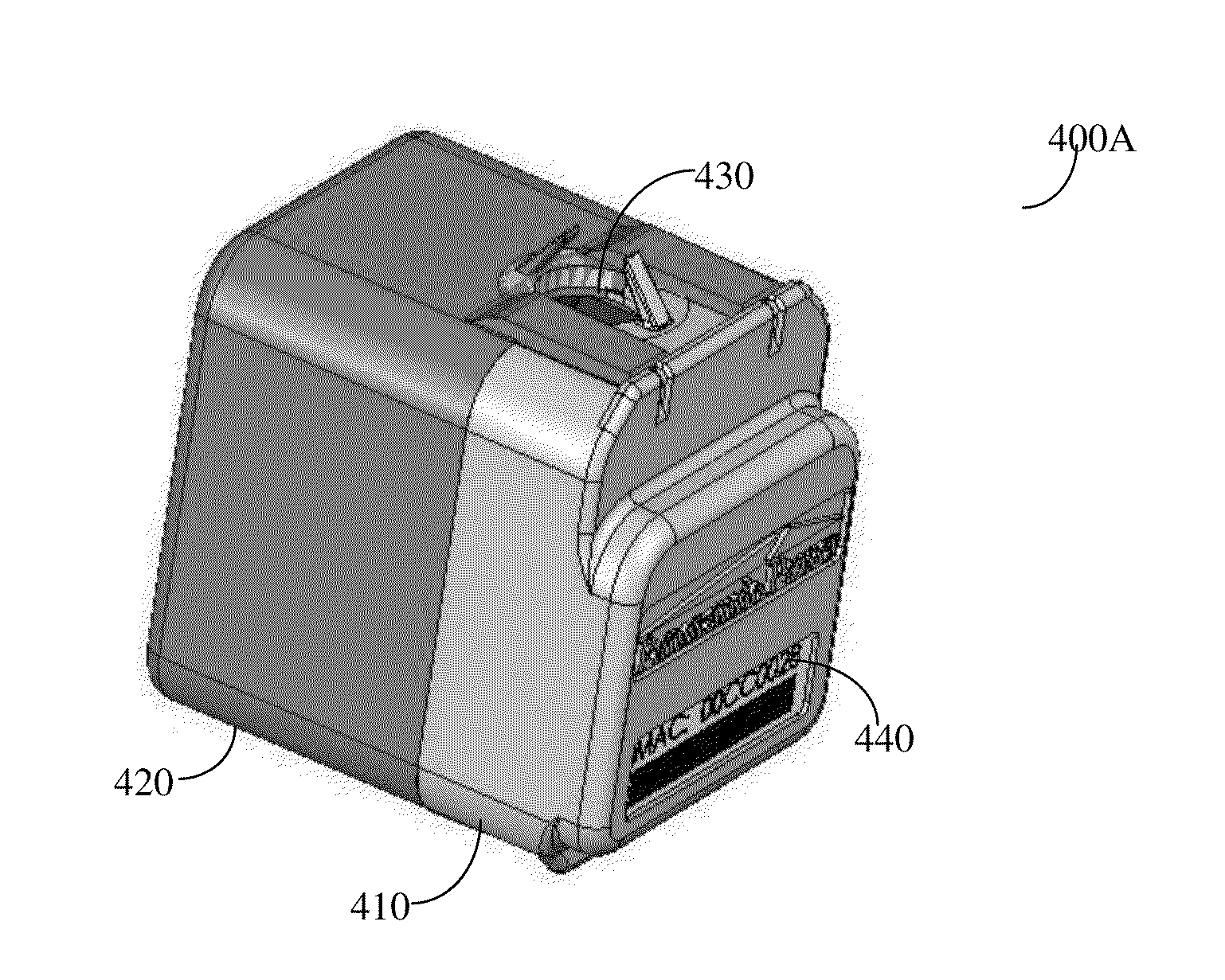
[0022]Apparatus and methods are provided for the measurement of power consumption at points of interest, such as circuit breakers, machines and the like. Accordingly, means are provided for measurement of power consumption for each electrical sub-network that is controlled by a circuit breaker. Each apparatus is enabled to communicate its respective data, in an environment of a plurality of such apparatuses, to a management unit which is enabled to provide finer granularity power consumption profiles. Challenges of measuring relatively low supply currents, wireless operation in an environment of a large number of apparatuses, and self-powering are addressed.

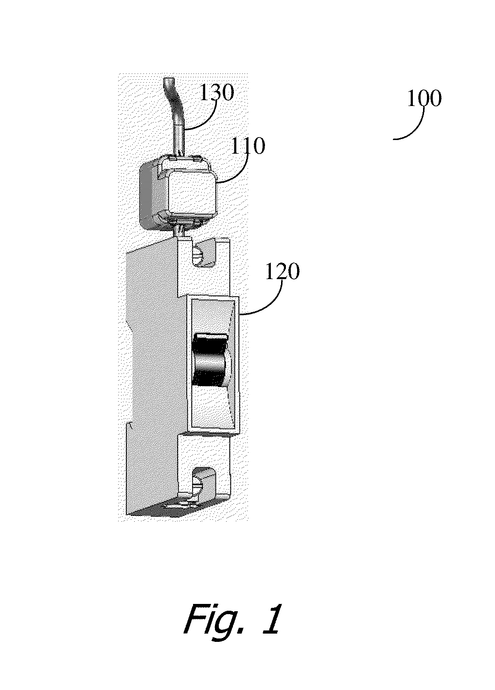
[0023]Reference is now made to FIG. 1 where an exemplary and non-limiting system 100 is equipped with a compatible self-powered power sensor (SPPS) 110 deployed in accordance with the invention. The SPPS 110 is designed to fit either above or below the circuit breaker 120 which is of standard size such that it fits into current c...


PUM


Abstract

Apparatus and methods are provided for electrical parameter measurements at points of interest, such as circuit breakers, machines, and the like. The devices which comprise of components that may require corrections, such as the errors induced by, but not limited to, the use of a split core mounted around a current carrier, and hence calibration coefficients are provided based on test, measurements and/or calculations respective of the devices. These coefficients may be stored in a database for retrieval when calibration of measurements received from a measuring device. In one embodiment at least one of the calibration coefficients is stored on the measuring device.

Description

CROSS-REFERENCE TO RELATED APPLICATIONS[0001]This application claims the benefit of U.S. Provisional Patent Application No. 61 / 802,686, filed on Mar. 17, 2013, and is a continuation-in part of U.S. patent application Ser. No. 13 / 301,453, filed Nov. 21, 2011, which claims the benefit of U.S. Provisional Patent Application No. 61 / 492,401 filed Jun. 2, 2011, and is a continuation-in-part of U.S. patent application Ser. No. 12 / 760,867 filed Apr. 15, 2010, which claims the benefit of U.S. Provisional Patent Application No. 61 / 169,750 filed Apr. 16, 2009 and U.S. Provisional Patent Application No. 61 / 272,216 filed Sep. 2, 2009, all of which are included herein by reference for all that they contain.BACKGROUND OF THE INVENTION[0002]1. Field of the Invention[0003]This invention generally relates to the measurement of power consumption and more specifically for calibration and error correction of split core current transformers used in non-intrusive and self-powered measurement devices.[0004...

Claims


Application Information

Patent Timeline
IPC IPC(8): G01R35/00G01R15/18
CPCG01R15/186G01R35/005G01R21/133G01R22/063
Inventor SHAMIR, ADIREVED, ITAY
Owner PANORAMIC POWER
Why Eureka
Try Eureka