
Location-based communication and interaction system

a communication and interaction system technology, applied in the field of location-based communication and interaction system, can solve problems such as confusion, missed sales opportunities, and miscommunication

Inactive Publication Date: 2014-07-17
SOCIAL ORDER
View PDF4 Cites 85 Cited by
  • Summary
  • Abstract
  • Description
  • Claims
  • Application Information

AI Technical Summary

Benefits of technology

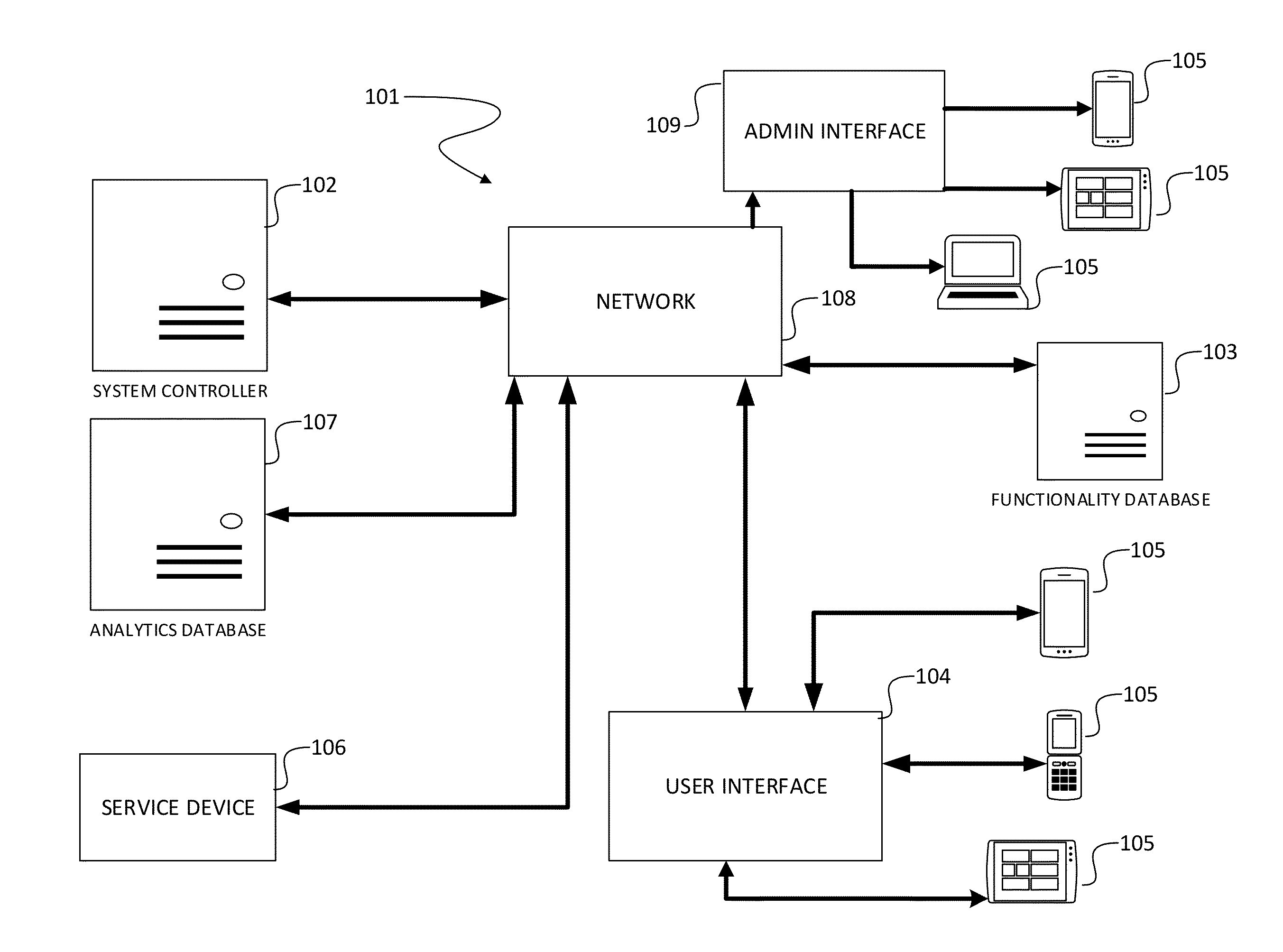
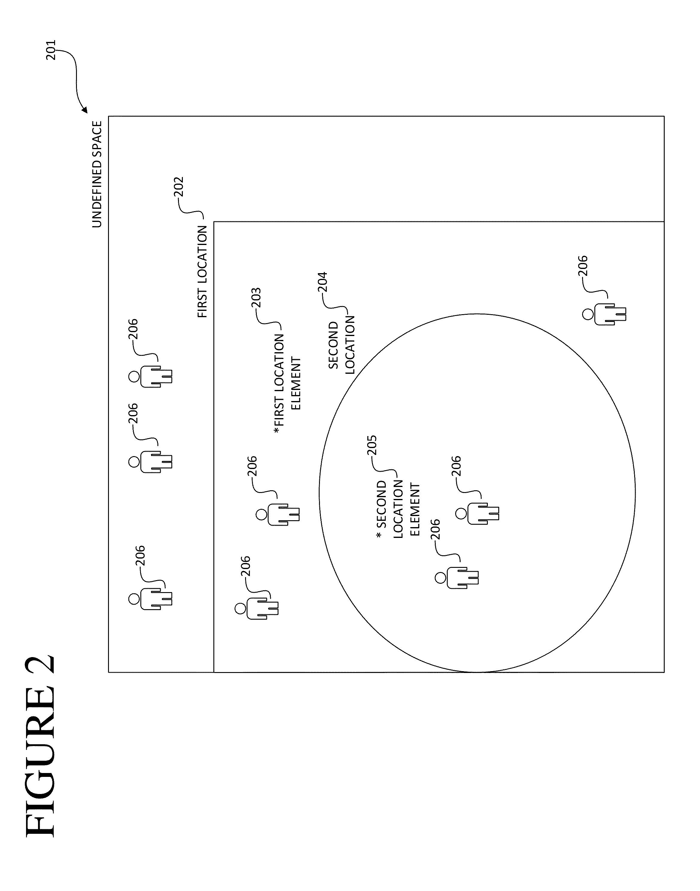
The present invention provides a system and method for creating location-based communication and interaction features. The system includes a database, a system controller, and two user interfaces. The method involves associating each user interface with a unique identifier and assigning them to a physical location. The users can then send actions and the system controller will transmits the unique identifier to the other user. The first user will have access to the second user's feature set based on the unique identifier. The invention also allows administrators to modify the number of features in each feature set. The technical effects of this invention include improved convenience, efficiency, and flexibility for users and administrators alike.

Problems solved by technology

These methods would often lead to miscommunication, confusion and missed sales opportunities when staff could not attend to these areas on a busy night.

Method used


Image

  • Location-based communication and interaction system
  • Location-based communication and interaction system
  • Location-based communication and interaction system

Examples


first embodiment

[0094]Next, at step 503, the system records an action based on the input made by the user 206. At this point there are two different embodiments that provide varying steps for the remainder of this invention. Within the first embodiment, the method continues through step 504, where the system controller 102 associates a value with the action / input initiated by the user 206. This value is predetermined by the administrator and can either reside within the functionality database 103 or the analytics database 107. This value is used by the system in order to generate a numeric total value to the actions initiated by the user. Based on this value generated by the user, the system 101 at step 505 associates a user 206 with a predefined group value based on the particular total values within the system 101. These value totals are stored either within the functionality database 103 or the analytics database 107 and are used in order to determine a particular “loyalty” or user level within ...

second embodiment

[0095]Within the invention, the system 101 will generate a set of activity data based on all the actions initiated by a user at step 507. This set of activity data will group particular actions together and also associate them based on their time, location, and additional metrics as predefined within the system 101. Next, at step 508, the system 101 will compare the set of activity data with a set of control data stored within the system. The set of control data may either be within the functionality data 103 or within the analytics database 107. This set control data will be predefined within the system in order to develop a comparison with the set of activity data generated by the user.

[0096]Next, at step 509, the system 101 will general a signal based on the statistical results between the set of activity data and the set of control data. These statistical results may include average and deviations from norms established within the set of control data for a particular action. Suc...


PUM


Abstract

A system comprising a database containing first and second location elements, a feature set, and a first unique identifier associated with the second location element; a system controller coupled to the database and configured to establish the first location element with a first physical location, establish the second location element with a second physical location and associate the first unique identifier with the second location element; and a user interface coupling a first user device with the system controller, the first user device associated with the first location element; and the system controller being further configured to transmit an initiated action between the first and second user, to transmit the unique identifier to the first user in relation to the action from the second user, and to associate the first user with the second location element based on the possession of the unique identifier by the first user after transmission.

Description

CROSS REFERENCE TO RELATED APPLICATIONS[0001]This application claims the benefits of U.S. Provisional Application No. 61 / 753,825 entitled SOCIAL ORDER APPLICATION, and filed on Jan. 17, 2013, the entirety of which is incorporated herein by reference.[0002]This application is related to and incorporates by reference related U.S. Non-Provisional application Ser. No. (N / A) entitled SYSTEM AND METHOD OF PROVIDING COMMUNICATION RECOMMENDATIONS (Attorney Docket No. 060518.00008) filed on Dec. 20, 2013, U.S. Non-Provisional application Ser. No. (N / A) entitled SOCIAL INTELLIGENCE SYSTEM AND METHOD (Attorney Docket No. 060518.0009) filed on Dec. 20, 2013, and U.S. Non-Provisional application Ser. No. (N / A) entitled SYSTEM AND METHOD OF GENERATING MICRO-SOCIAL ENVIRONMENTS (Attorney Docket No. 060518.0010) filed on Dec. 20, 2013.COPYRIGHT NOTICE[0003]A portion of this disclosure contains material that is subject to copyright protection. The copyright owner has no objection to the facsimile re...

Claims


Application Information

Patent Timeline
Patent Type & Authority Applications(United States)
IPC IPC(8): H04L29/08
CPCH04L67/16G06Q30/0641G06Q50/01H04W4/029H04W4/02H04L51/52H04L12/1831H04L12/1813
Inventor TRUMMER, MARCUSBEARD, PATRICKJOHNSON, MIKE
Owner SOCIAL ORDER
Learn More