System and method including laboratory product transport element

a technology of transport element and laboratory product, which is applied in the field of system and method including laboratory product transport element, can solve the problems of complex layout and high demand for mechanical and electronic components, drive drives for conveyors are often very space-intensive, and conventional systems require large complicated mechanisms

Active Publication Date: 2014-07-24
BECKMAN COULTER INC
View PDF8 Cites 53 Cited by
  • Summary
  • Abstract
  • Description
  • Claims
  • Application Information

AI Technical Summary

Benefits of technology

[0012]Some embodiments include methods for operation of a laboratory transport system in which an objective is stipulated to a laboratory product transport element. The control unit of the laboratory product transport element generates drive signals for the drive devices of the laboratory product transport element by means of a transfer path geometry stored in a memory of the laboratory product transport element and the entered objective.

Problems solved by technology

This produces a complex layout and a high demand for mechanical and electronic components.
The drives for the conveyor are often very space-intensive.
These conventional systems require large complicated mechanisms, which take space underneath or adjacent to the puck path.
Conveyor drive systems have large areas that are not usable for the transport of pucks at deflections of the chain / belt.
It is therefore difficult to implement branching at right angles.
In addition, during a change of the puck from a chain or belt to another chain or other belt, a large vibration can occur for the puck, which is not tolerable for many sample materials.
In conventional systems, the mechanical components needed to operate the chain or belt conveyor system or the magnetic transport system is complex.
If an element, like a switch, brake or sensor, fails in a conventional system, this can lead to shutdown of the complete transport system, until the disturbance has been eliminated by a service technician.
Finally, changing paths in conventional conveyor systems can be mechanically demanding and expensive.
That is, when using a conventional conveyor system, the ability to transport samples according to different protocols is limited, because of the physical constraints provided by such conveyor systems.

Method used


Image

  • System and method including laboratory product transport element
  • System and method including laboratory product transport element
  • System and method including laboratory product transport element

Examples


Embodiment Construction

[0054]The following detailed description may utilize terms as provided below to describe different aspects of different embodiments.

[0055]A “laboratory product” may refer to a variety of different containers that may be transported within a laboratory transport system. Examples of such containers include, but are not limited to, a test tube, a sample tube, a sample container, or any container that may be configured to hold a laboratory sample. In addition, a laboratory product may be capped or uncapped in different situations. Also, in some embodiments of the invention, laboratory product may also be pre-centrifuged prior to being transported.

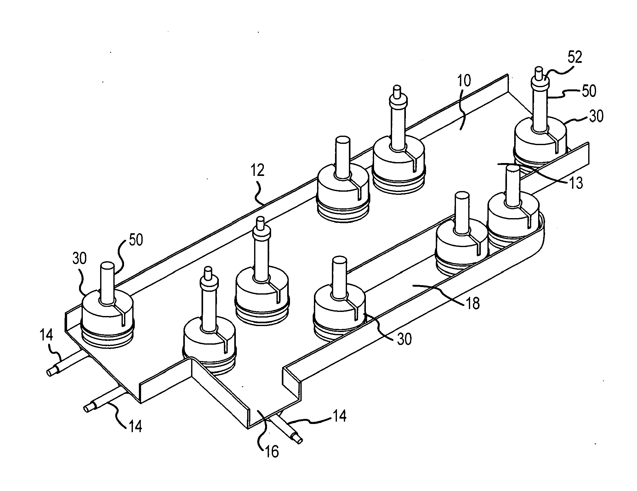
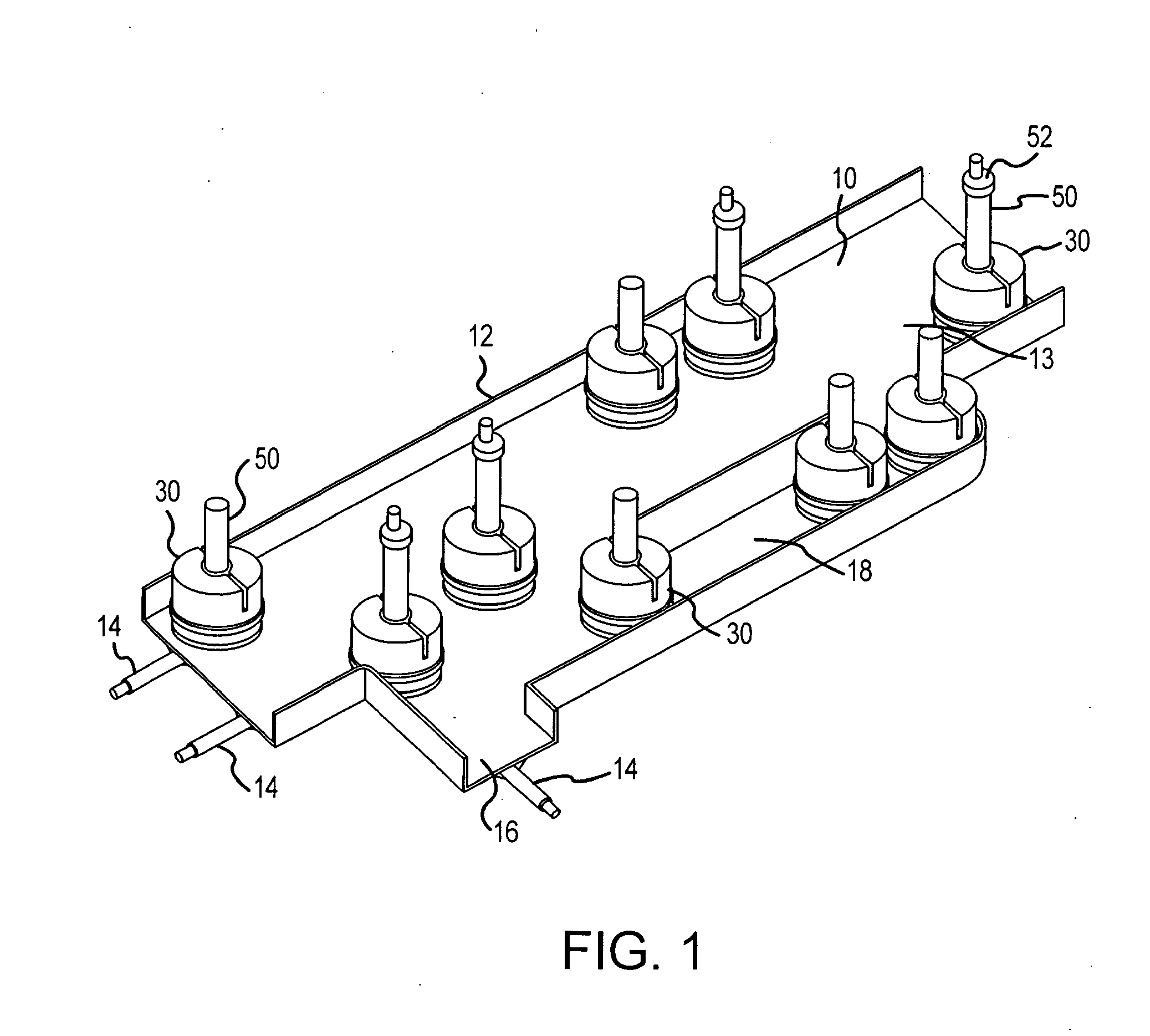
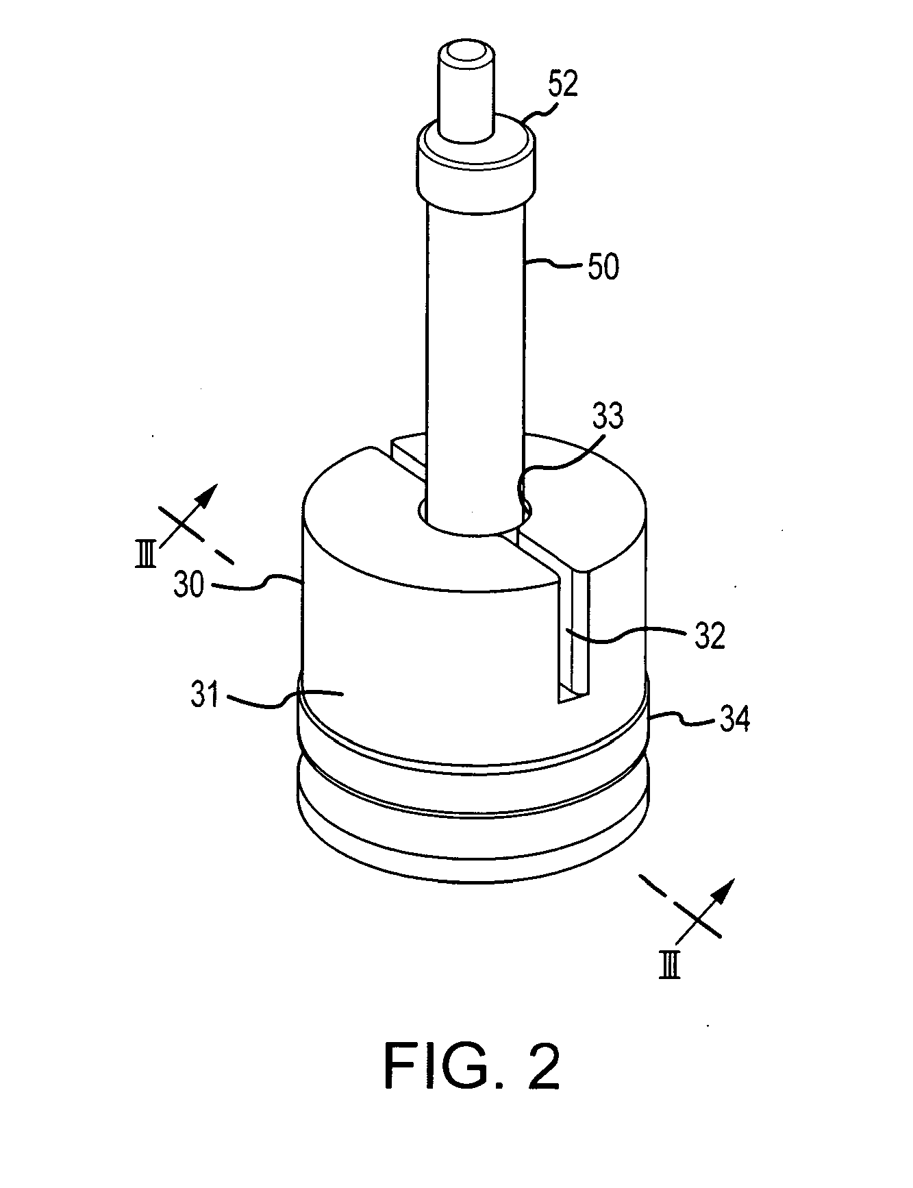
[0056]A “laboratory product transport element” may include a variety of different transport elements configured to transport a laboratory product within a laboratory transport system. A laboratory product transport element can transport a laboratory product (e.g., a sample tube) using any suitable mode of transport. Exemplary laboratory product...


PUM

PropertyMeasurementUnit
heightaaaaaaaaaa
heightaaaaaaaaaa
heightaaaaaaaaaa

Abstract

The invention concerns a laboratory product transport element for a laboratory transport system with an energy receiver and/or energy accumulator to provide drive power, at least one signal receiver to receive control signals, a control unit to generate drive signals as a function of at least one control signal obtained from the at least one signal receiver, movement devices for independent movement of the laboratory product transport element on a transfer path as a function of the drive signals of the control unit, in which the drive devices are driven by the drive power and at least one holder to hold a laboratory product being transported. The invention also concerns a laboratory transport system with at least one laboratory product transport element according to an embodiment of the invention and a transfer path arrangement. The invention also concerns methods for operation of laboratory transport systems according to an embodiment of the invention.

Description

CROSS-REFERENCE TO RELATED APPLICATIONS[0001]This application is a non-provisional of and claims the benefit of the filing date of U.S. provisional patent application No. 61 / 486,126 filed on May 13, 2011, which is herein incorporated by reference in its entirety for all purposes.BACKGROUND[0002]Embodiments of the present invention relate to a laboratory transport system used in automated medical laboratory in-vitro diagnostic systems for handling patient samples. The transport system according to an embodiment of the invention comprises at least one transfer path arrangement and at least one laboratory product transport element which transports laboratory products, such as patient samples, and methods for its operation. Embodiments of the invention also relate to a laboratory product transport element and a transfer path arrangement for a laboratory transport system.[0003]Laboratory transport systems such as gripper systems are used in medical laboratories to transport sample tubes ...

Claims


Application Information

Patent Timeline
Patent Type & Authority Applications(United States)
IPC IPC(8): B65G47/74B65G35/00B65G43/00
CPCB65G47/74B65G35/00B65G43/00B01L3/5082B01L9/06B01L2200/18B01L2300/023G01N35/04G01N2035/0401G01N2035/0467G01N2035/0475G01N2035/0489
Inventor EBERHARDT, MICHAELMUELLER, MARTINWIESSNER, SEBASTIAN
Owner BECKMAN COULTER INC
Why Eureka
Try Eureka