Overvoltage Protection Method for Backlight Driver

a backlight driver and overvoltage protection technology, applied in the direction of emergency protective arrangements for limiting excess voltage/current, electrical devices, etc., can solve the problems of reducing the lifetime of a convertor in the circuit, affecting the components of the driving circuit, and abrupt overvoltage, so as to reduce the overvoltage protection level and prolong the lifetime of components

Inactive Publication Date: 2014-07-24
SHENZHEN CHINA STAR OPTOELECTRONICS TECH CO LTD
View PDF6 Cites 1 Cited by
  • Summary
  • Abstract
  • Description
  • Claims
  • Application Information

AI Technical Summary

Benefits of technology

[0034]A benefit of the present invention is described as below: by detecting signals of dimming control to conduct different reference voltage to compare voltage, this overvoltage protection method of backlight driver succeeds in setting up different ove

Problems solved by technology

However, determining the overvoltage protection point by driving voltage of LED series circuit 100 under 3D mode is technically defective as described below: when overvoltage protection is triggered by some unusual causes, if output volt

Method used


Image

  • Overvoltage Protection Method for Backlight Driver
  • Overvoltage Protection Method for Backlight Driver
  • Overvoltage Protection Method for Backlight Driver

Examples


Embodiment Construction

[0040]The drawings illustrate embodiments of the invention and, together with the description, serve to explain the principles of the invention.

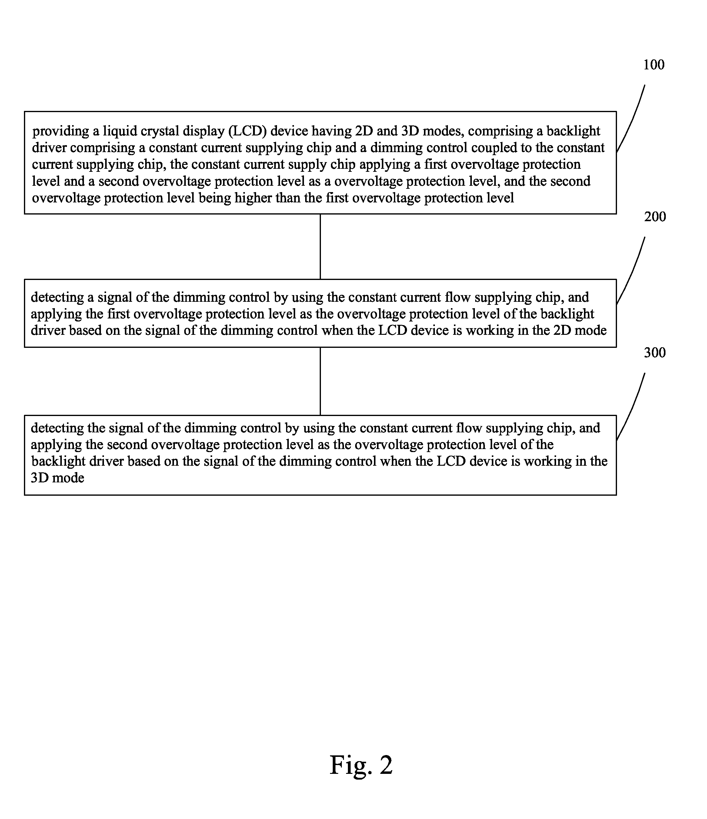
[0041]Please refer to FIG. 2 and FIG. 3. The present invention provides an overvoltage protection method of backlight driver comprises the following steps:

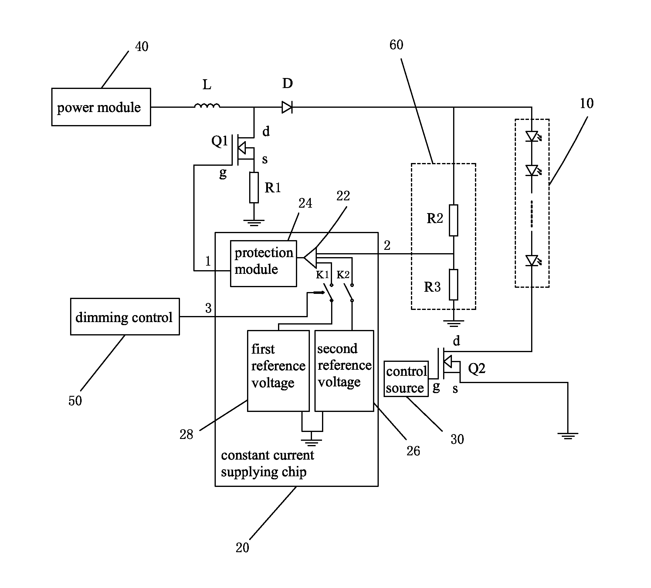
[0042]Step 100: Provide a LCD device (not shown) having 2D and 3D modes. A backlight driver comprising a constant current supplying chip 20 and a dimming control 50 coupled to the constant current supplying chip 20. The constant current supplying chip 20 applies a first overvoltage protection level and a second overvoltage protection level as overvoltage protection level, and the second overvoltage protection level is higher than the first overvoltage protection level.

[0043]The backlight driver also comprises: a power module 40, an inductance L coupled to the power module 40, a voltage dividing module 60, a rectifying diode D coupled between the inductance L and the voltage dividing module...


PUM


Abstract

An overvoltage protection method for backlight driver includes: providing an LCD device having 2D and 3D modes, comprising a backlight driver comprising a constant current supplying chip and a dimming control coupled to the constant current supplying chip, the constant current supply chip applying a first overvoltage protection level and a second overvoltage protection level as a overvoltage protection level; detecting a signal of the dimming control by using the constant current flow supplying chip, and applying the first overvoltage protection level as the overvoltage protection level based on the signal of the dimming control when the LCD device is in the 2D mode; and detecting the signal of the dimming control by using the constant current flow supplying chip, and applying the second overvoltage protection level as the overvoltage protection level based on the signal of the dimming control when the LCD device is in the 3D mode.

Description

BACKGROUND OF THE INVENTION[0001]1. Field of the Invention[0002]The present invention relates to liquid crystal display device field, in particular, to a method for driving an LED backlight source in a liquid crystal display device.[0003]2. Description of the Prior Art[0004]A liquid crystal display (LCD) presenting advantages over thinness, low power consumption and non-radiation, is widely used. Most LCDs in present market are backlight type LCDs, comprised of liquid crystal panel and backlight module. The liquid crystal panel has liquid crystal molecules between two paralleling glass substrates. Light from the backlight module is refracted depending on an alignment of the liquid crystal molecules controlled by voltage drop between the two glass substrates through many vertical and horizontal tiny wires thereon, thereby displaying images. The backlight module is one of the key components of LCD device, because normal display of image is provided by light from the backlight module, ...

Claims


Application Information

Patent Timeline
IPC IPC(8): H02H9/04
CPCH02H9/04H02H9/041Y02B20/30H05B45/3725H05B47/24
Inventor HU, ANLELI, FEI
Owner SHENZHEN CHINA STAR OPTOELECTRONICS TECH CO LTD
Why Eureka
Try Eureka