Methods for energy-efficient unicast and multicast transmission in a wireless communication system

Active Publication Date: 2014-07-24
TEXAS INSTR INC
View PDF18 Cites 85 Cited by
  • Summary
  • Abstract
  • Description
  • Claims
  • Application Information

AI Technical Summary

Problems solved by technology

Unfortunately, current base stations typically transmit control channels and cell-specific referenc

Method used


Image

  • Methods for energy-efficient unicast and multicast transmission in a wireless communication system
  • Methods for energy-efficient unicast and multicast transmission in a wireless communication system
  • Methods for energy-efficient unicast and multicast transmission in a wireless communication system

Examples


Embodiment Construction

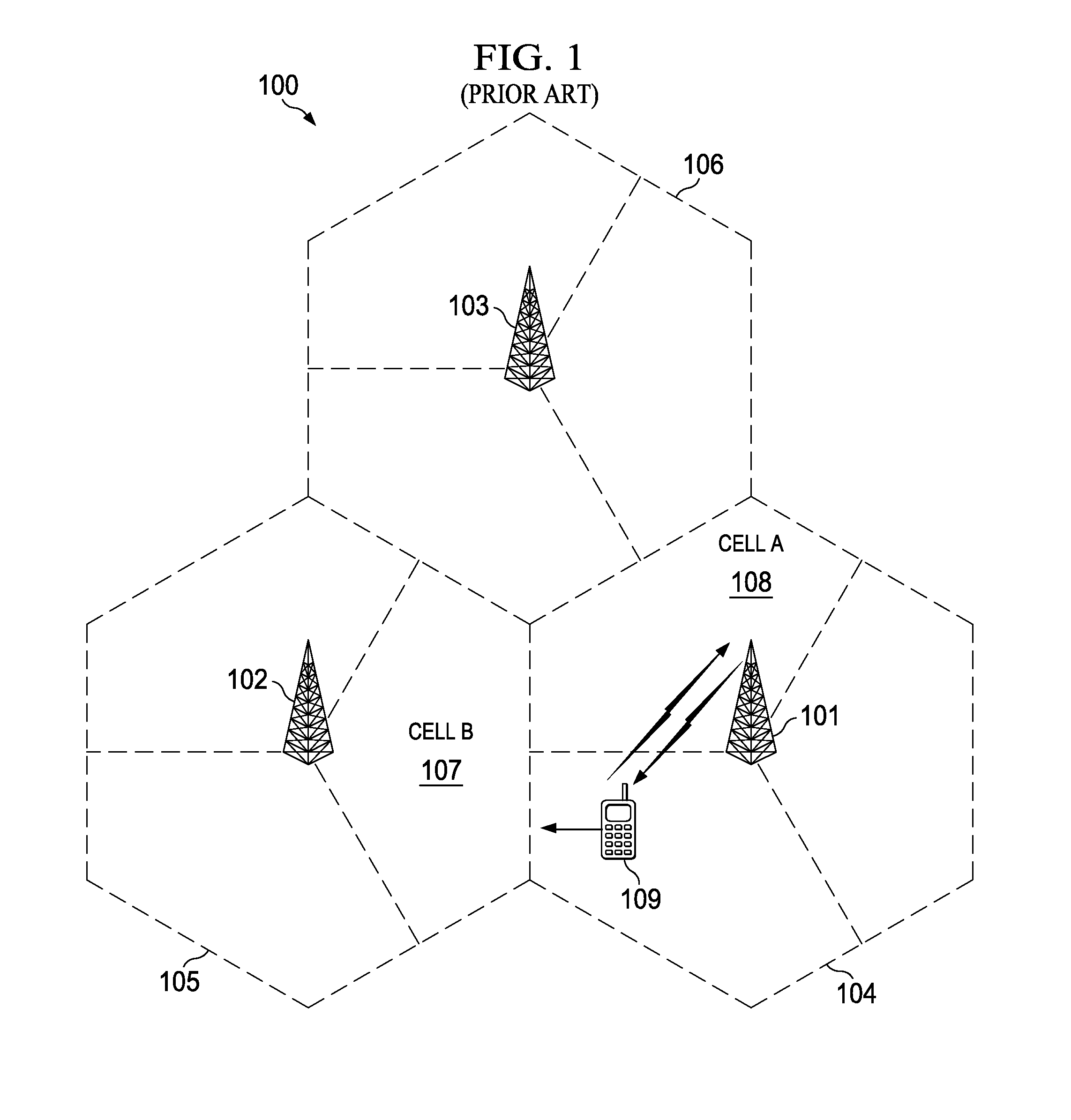
[0020]As cellular networks evolve to cope with this explosive growth in cellular data traffic it has been observed that bottlenecks occur because much of the traffic is localized to hotspots in both indoor and outdoor deployment scenarios. Heterogeneous networks are increasingly becoming popular, wherein small cells controlled by low power base stations are deployed to boost capacity in hotspots and / or improve cellular coverage. In the Third Generation Partnership Project (3GPP) Long Term Evolution (LTE) system, a base station, also known as an evolved NodeB (eNB), always transmits a cell-specific reference signal (CRS) and a time-multiplexed Physical Downlink Control Channel (PDCCH). But always transmitting a cell-specific reference signal and a time-multiplexed Physical Downlink Control Channel (PDCCH) becomes problematic as traffic and demand increases.

Description of an Evolved Transmission Format

[0021]The 3GPP radio access network (RAN) standardization body is taking steps to ad...


PUM


Abstract

A method for time multiplexing subframes on a serving cell to a user equipment, wherein one set of subframes operate with the legacy LTE transmission format and one set of subframes operate with an evolved transmission format comprising reduced density CRS transmission without a PDCCH control region.

Description

CLAIM TO PRIORITY UNDER 35 U.S.C. 119[0001]The present application claims priority to and incorporates by reference U.S. provisional application Nos.: 61 / 754,429, filed on Jan. 18, 2013; 61 / 767,510, filed on Feb. 21, 2013; 61 / 767,515, filed on Feb. 21, 2013; 61 / 804,089, filed on Mar. 21, 2013; 61 / 804,310, filed on Mar. 22, 2013; 61 / 806,269, filed on Mar. 28, 2013; 61 / 808,784, filed on Apr. 5, 2013; and 61 / 833,726, filed on Jun. 11, 2013.FIELD OF THE INVENTION[0002]This invention generally relates to wireless communications, and in particular to User Equipment connected to a base station.BACKGROUND OF THE INVENTION[0003]Cellular communication networks incorporate a number of wireless terminal devices and a number of base stations for the purpose of providing communications services such as telephony, data, video, messaging, chat and broadcast. A number of wireless terminals can be connected to a serving cell that is controlled by a base station (BS). Typical access schemes employed i...

Claims


Application Information

Patent Timeline
IPC IPC(8): H04W72/00
CPCH04W72/005H04L5/0044H04L5/005H04L5/0051H04L5/0053H04L5/0064H04L5/001Y02D30/70H04L5/0048
Inventor EKPENYONG, ANTHONY EDETBENDLIN, RALF MATTHIASONGGOSANUSI, EKO NUGROHOCHEN, RUNHUA
Owner TEXAS INSTR INC
Why Eureka
Try Eureka