System and method for monitoring entry of object into surrounding area of robot

a robot and object technology, applied in the field of monitoring system and method that monitor the entry of objects into the surrounding area of robots, can solve the problems of affecting workability, affecting the effective use of the site, and workability has to be complicated and time-consuming, so as to eliminate lots of work and time, improve workability, and improve work efficiency

Active Publication Date: 2014-07-24
DENSO WAVE INC
View PDF13 Cites 49 Cited by
  • Summary
  • Abstract
  • Description
  • Claims
  • Application Information

AI Technical Summary

Benefits of technology

[0011]According to this configuration, entry of a new object into the operating area is monitored, the operating area being set up to enclose the movable range of the robot. When entry of a new object into the operating area is determined to have occurred, a request for stopping the robot is issued to the robot control unit that controls the robot. Thus, without setting up a fence around the robot, the robot at work is prevented from interfering with the new object. In this way, workability will not be impaired, unlike the case where a fence is set up.
[0012]Further, this monitoring system, which dispenses with setting up a fence around the robot, can eliminate lots of work and time that would be involved in setting up a fence around the robot.
[0013]For example, when a fence is provided around the robot, there may be a necessity, sometime after providing the fence, for displacing the fence because of a little change in the location of the robot. In order to avoid such displacement, the fence tends to be set up with an exceedingly large margin, tending to impair effective usage of the site. In this regard, this monitoring system dispenses with setting up a fence around the robot. In addition, in the event that the location of the robot is changed, the position of setting up the operating area may only have to be changed. With only the change in the position of setting up the operating area, monitoring can be targeted to a minimum adequate area suitable for the new location of the robot. In this way, effective usage of the site is enhanced.
[0014]Further, according to this configuration, visible light is irradiated from a level higher than that of the robot toward at least an outer edge portion of at least one of the operating area and the predetermined area set up around the operating area. Thus, a strong alert is called to the operating area and the predetermined area around the operating area, thereby effectively suppressing unintentional entry of an object into the operating area.

Problems solved by technology

However, when a worker of the facility, for example, has to come close to the robot by necessity, the worker has to take complicated and time-consuming actions, such as unlocking and opening a door provided in the fence for entry into a region enclosed by the fence, and closing and locking the door after the entry.
Therefore, provision of the fence has raised a problem of impairing workability.
In order to avoid such displacement, the fence tends to be set up with an exceedingly large margin, tending to impair effective usage of the site.
Accordingly, in this period, it will be difficult for a person, such as a worker, to empirically learn the location of the operating area.
Thus, a strong alert is supplied to the operating area, and thus there will be a low probability that a worker enters the operating area without noticing its presence and unavoidably stopping the robot.
Accordingly, in this period, it will be difficult for a person, such as a worker, to empirically learn the location of the operating area.
Thus, a strong alert is supplied to the final confirmation area, and thus there will be a low probability that a worker enters the final confirmation area without noticing its presence and further enters the operating area inside the final confirmation area which would unavoidably stop the robot.

Method used


Image

  • System and method for monitoring entry of object into surrounding area of robot
  • System and method for monitoring entry of object into surrounding area of robot
  • System and method for monitoring entry of object into surrounding area of robot

Examples


first embodiment

A. First Embodiment

A-1. Configuration of Monitoring System

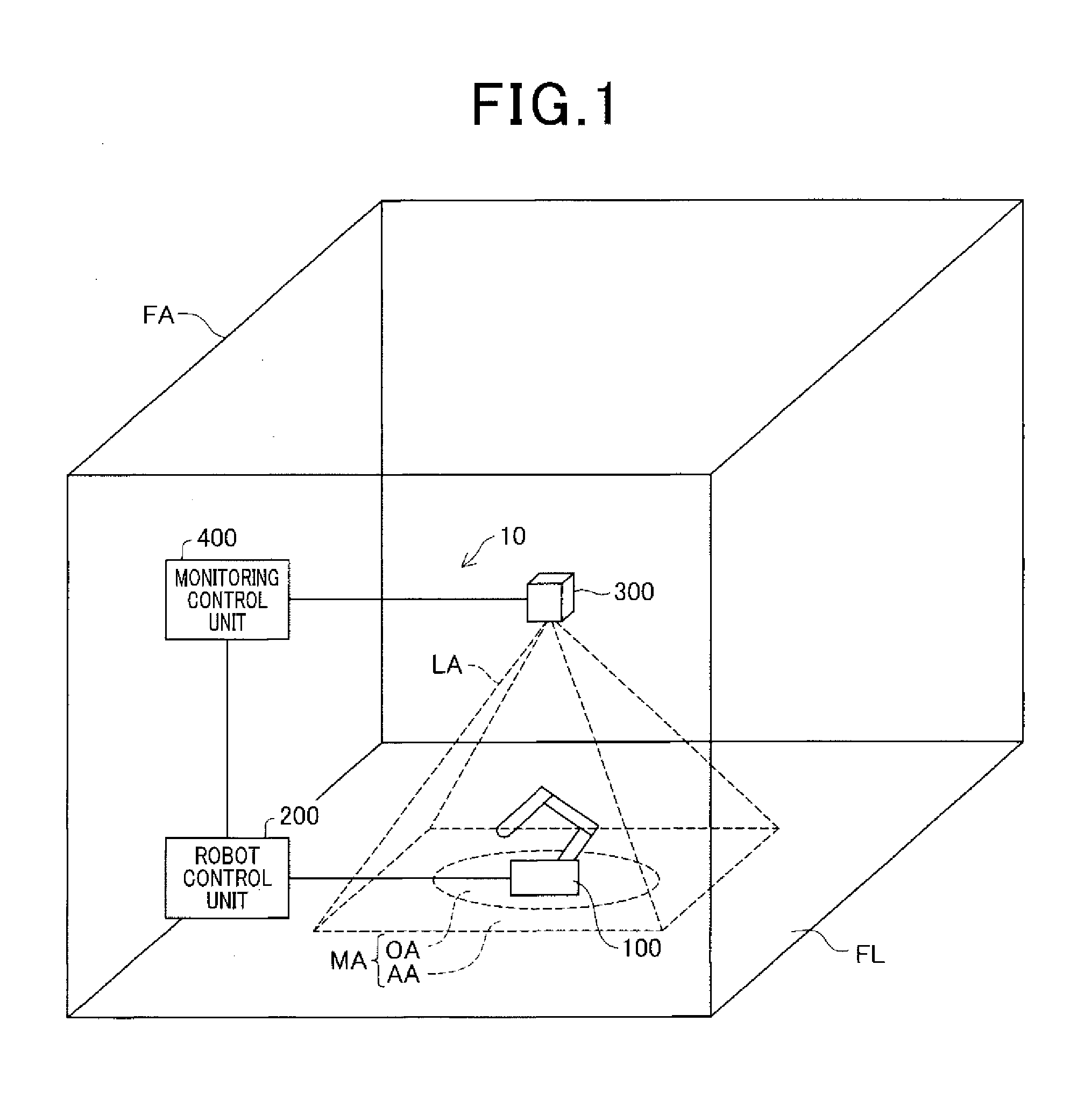
[0045]FIG. 1 is a schematic diagram illustrating a monitoring system 10, according to the first embodiment. The monitoring system 10 of the present embodiment monitors entry of an object (e.g., a person) into the surrounding area of a robot 100 and stops the movement of the robot 100 as necessary.

[0046]In the present embodiment, the robot 100 is an industrial articulated robot having a plurality of joint axes and set up on a floor surface FL of a factory FA. The robot 100 is connected to a robot control unit 200 via a control cable. The robot control unit 200 is configured as a computer that includes a central processing unit (CPU) and a memory. The robot control unit 200 controls movement of the robot 100 by actuating motors provided at respective joints of the robot 100.

[0047]The robot 100 has a surrounding area in which an operating area OA and an alert area AA are set up. The operating area OA is a three-dimensional area ...

second embodiment

B. Second Embodiment

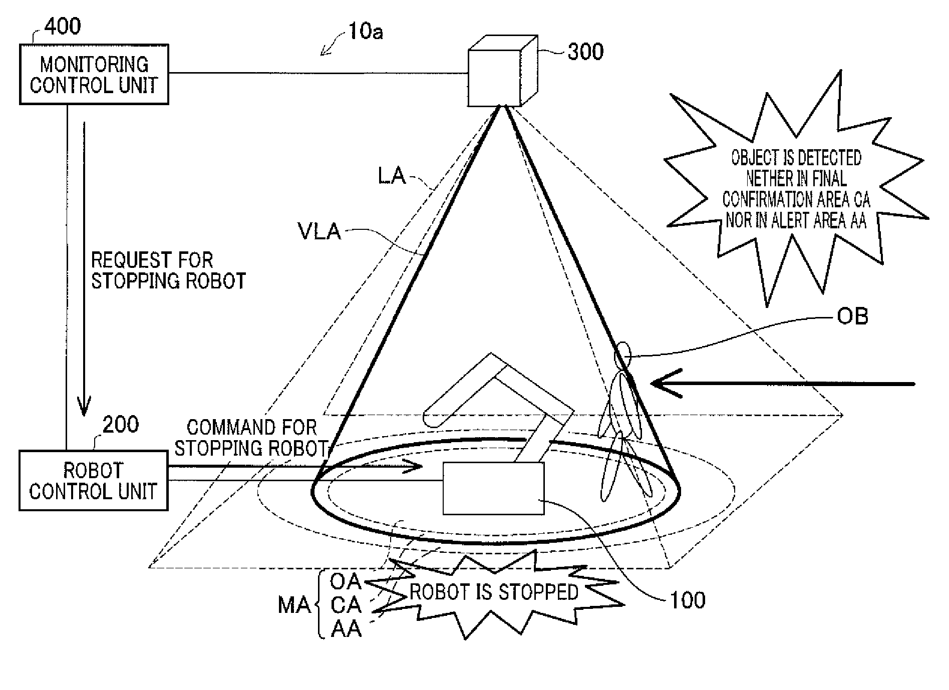
[0090]FIG. 8 is a schematic diagram illustrating a monitoring system 10a according to the second embodiment. The second embodiment is different from the first embodiment in the configuration of the monitored area MA provided around the robot 100. Specifically, in the second embodiment, the monitored area MA is configured by an operating area OA, a final confirmation area CA and an alert area AA.

[0091]The operating area OA is a three-dimensional area which is set up to enclose a movable range of the robot 100. The final confirmation area CA is a three-dimensional area which is set up around the operating area OA. The alert area AA is a three-dimensional area which is set up around the final confirmation area CA.

[0092]In FIG. 8, the operating area OA, the final confirmation area CA and the alert area AA on the floor surface FL are shown by broken lines. Although the operating area OA, the final confirmation area CA and the alert area AA are set up, neither a fence ...


PUM


Abstract

A monitoring system monitors entry of an object into a surrounding area of a robot. The monitoring system includes visible light irradiation section, a sensor section and a monitoring control unit. The visible light irradiation section irradiates visible light from a level higher than that of the robot toward at least an outer edge portion of at least one of an operating area, which is set up to enclose a movable range of the robot, and a predetermined area which is set up around the operating area. The sensor section monitors entry of a new object, which is not registered in advance, into the operating area. The monitoring control unit issues a request for stopping the robot to a robot control unit that controls the robot, when entry of a new object into the operating area is detected by the sensor section.

Description

CROSS-REFERENCE TO RELATED APPLICATION[0001]This application is based on and claims the benefit of priority from Japanese Patent Application No. 2013-009948, filed on Jan. 23, 2013, the disclosure of which is incorporated herein in its entirety by reference.BACKGROUND[0002]1. Technical Field[0003]The present invention relates to a monitoring system and method that monitor entry of an object into the surrounding area of a robot.[0004]2. Related Art[0005]Robots are widely used such as in automated production facilities. In such automated production facilities, a robot at work is required to be prevented from interfering with an object (e.g., a person). In order to prevent such interference, a fence (also called “safety fence”) has generally been set up outside a movable range of the robot to limit entry of the object into this range (e.g., see JP-A-2005-081445).[0006]However, when a worker of the facility, for example, has to come close to the robot by necessity, the worker has to tak...

Claims


Application Information

Patent Timeline
Patent Type & Authority Applications(United States)
IPC IPC(8): B25J9/16
CPCB25J9/1697B25J9/1676G05B2219/40196G05B2219/40203
Inventor SAKABE, KOUJI
Owner DENSO WAVE INC
Why Eureka
Try Eureka