Test fixture for testing backplanes or populated circuit boards

a test fixture and backplane technology, applied in the direction of electronic circuit testing, measurement devices, instruments, etc., can solve the problems of high material cost of spring loaded contacts, high cost of dedicated arrangements for large, and high point count backplanes

Inactive Publication Date: 2001-02-27
XCERRA
View PDF21 Cites 57 Cited by
  • Summary
  • Abstract
  • Description
  • Claims
  • Application Information

AI Technical Summary

Benefits of technology

Since in the present invention the guide block conductive pins engage the translator pins and contact posts and are generally coaxially aligned with the contact posts, better and more stable electrical contact may be maintained between the translator pins and contact posts than is possible in the prior art. Additionally, the present invention substantially eliminates the risk of inadvertent connection of translator pins to wrong contact posts, each other, and the sidewalls of the connectors. Further advantageously, the present invention eliminates the need to use the translator pin routing and guiding structures of the prior art, thereby eliminating the expense and time associated with construction and utilization of such structures.
In a second and most preferred embodiment of the present invention, a large area probe plate is physically fastened to a translator fixture. In this embodiment, the large area probe plate is substituted for the guide block assembly of the first embodiment. The large area probe plate can employ a variety of length and force spring probes to reach up into connectors on the backplane and can have additional routed clearance plates for obstructions on the backplane. The large area probe plate is customized to fit the backplane of the unit under test which allows the translator fixture to be all one level and free from design complexity. Contact of the spring probes contained within the large area probe plate against the unit under test is parallel and perpendicular to the probe plate.

Problems solved by technology

There are a number of disadvantages, however, to dedicated testers, the most notable of which is cost.
The complexity of wiring dedicated fixtures, together with the relatively high material cost of spring loaded contacts makes the dedicated arrangement extremely expensive for large, high point count backplanes.
Further, revision changes in the unit under test cannot be easily accommodated and the serviceability and reliability of dedicated fixtures is somewhat lower than determined translator grid fixtures.
In these grid-type testers, fixturing is generally less complex and can be produced at a lower cost than in the customized wired test fixtures; but with a grid system, the grid interfaces and test electronics are substantially more complex and costly.
Translator fixtures, however, are less commonly used for testing backplanes than dedicated fixtures mainly because the software requirements are unique and beyond the capabilities of general purpose test fixture software.
Translator fixtures, however, suffer from a few disadvantages when compared to dedicated fixtures.
By their nature, grid based fixtures usually suffer from low tester channel utilization.
They also suffer from two additional problems wherein leaning translator pins cannot always reach up into shrouded connectors, and translator fixtures with multiple pin heights are difficult to design and assemble requiring many custom parts and significant engineering attention.
It has been found that prior art testing apparatus of the types discussed above are not well suited for testing of contact posts mounted in connectors having sidewalls which extend beyond the ends of the contact posts.
As a result, it often proved difficult to achieve good, stable electrical connection between the contact posts and the translator pins using prior art fixtures.
Additionally, due to the tilting required to make contact to the uniform grid of the tester, the translator pins are rarely coaxial with the contact posts when they contact the posts.
Since the contact posts usually are spaced very close together in the connector, this can cause translator pins to inadvertently become electrically connected to the wrong contact posts, and / or to each other.
These can result in erroneous test results, damage to the circuit board, and / or damage to the testing apparatus.
While such techniques were able somewhat to reduce the risk of occurrences of inadvertent connection of translator pins to wrong contact posts, each other, and the sidewalls of the connectors, such drilling compromised the rigidity of the structure laterally, and often resulted in false opens and shorts during the testing process.
Additionally, such techniques added to costs.

Method used


Image

  • Test fixture for testing backplanes or populated circuit boards
  • Test fixture for testing backplanes or populated circuit boards
  • Test fixture for testing backplanes or populated circuit boards

Examples


embodiment 14

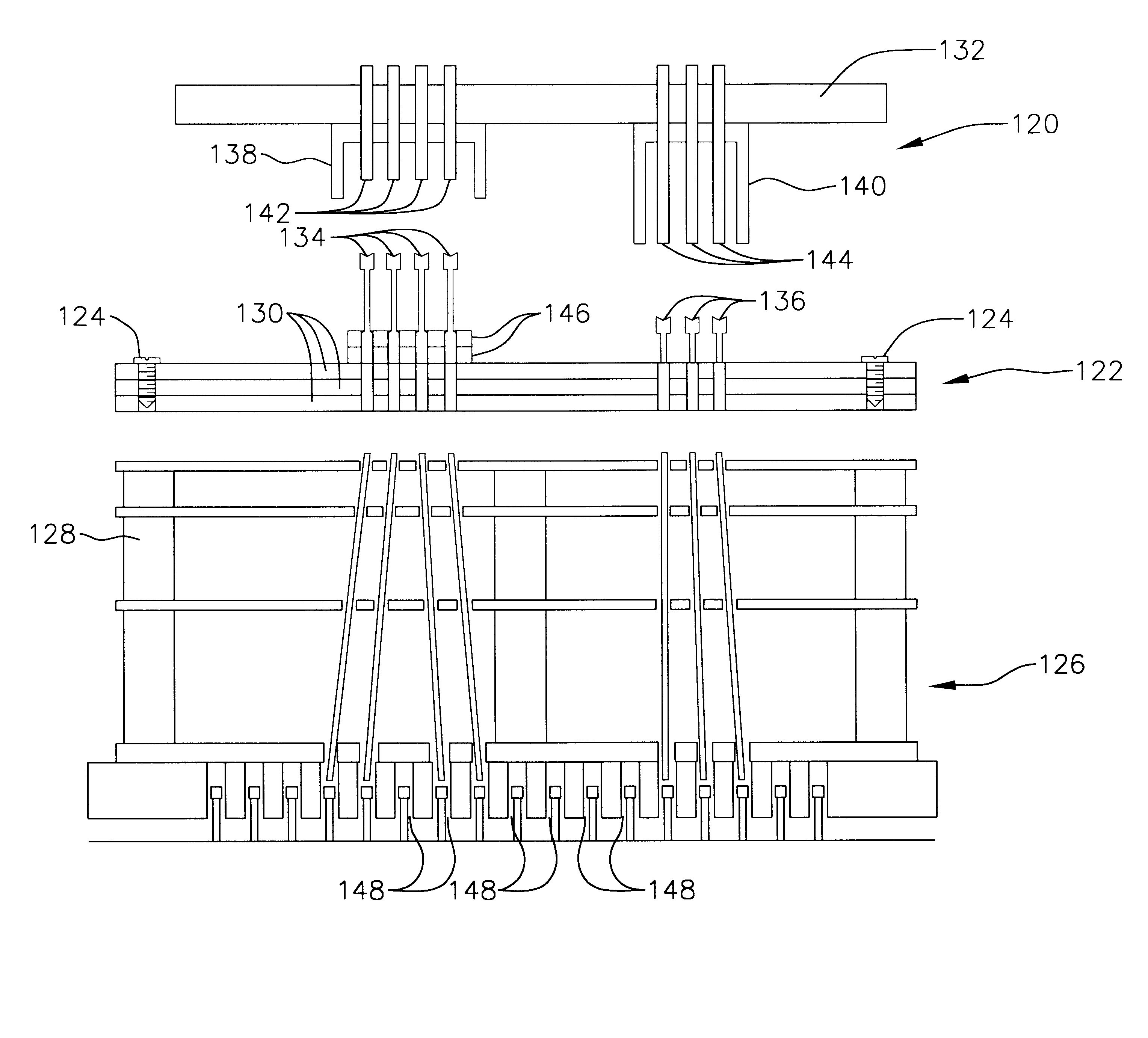
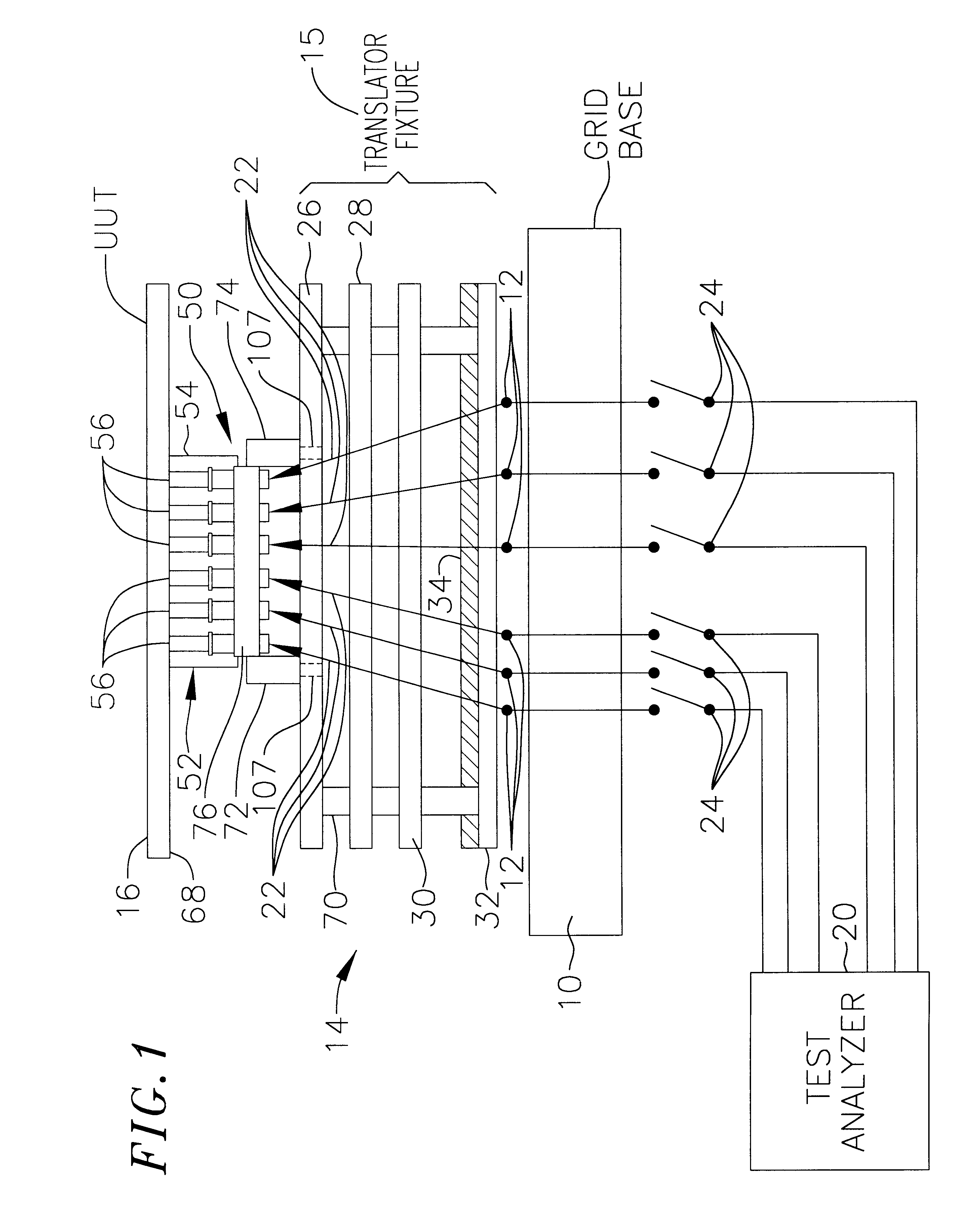
Translator fixture 15 includes a series of vertically spaced-apart and parallel translator plates 26, 28, 30, 32, which may include a top (outermost) plate 26, an upper plate 28 spaced a short distance below the top plate 26, one or more intermediate plates 30, and a grid facing plate 32 at the bottom of the translator fixture. The translator plates are supported in parallel, vertically spaced apart positions by rigid posts 70 that hold the fixture 15 together as a rigid unit. The fixture 15 also includes an array of standard translator pins such as tilt pins represented schematically at 22 extending through holes (not shown) in the translator plates. FIG. 1 represents only six translator pins for simplicity, but it should be understood that any number of such translator pins 22 may be used depending upon the number of posts 56 and other contact points (not shown) to be tested on the board 16. The tilt pins extending through the base plate 32 of the fixture 15 are in alignment with ...

first embodiment

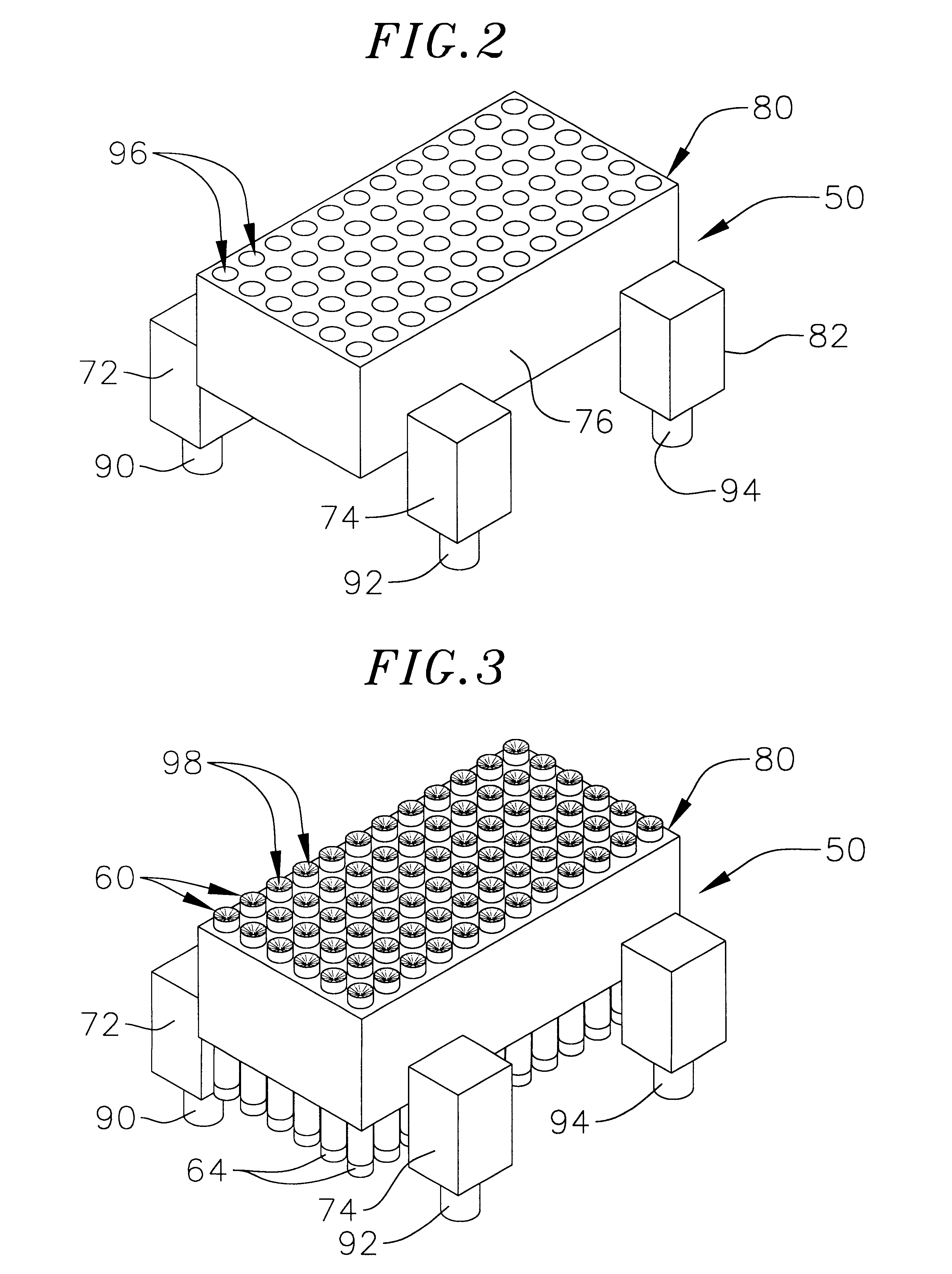
Completing the system of the first embodiment is a guide block 50 which is positioned directly beneath the distal ends of the posts 56 and which, in preferred form, comprises a rectangular, molded or machined plastic block 76 having a top surface plan 80 which is undersized compared to the opening 120 of the connector 52. Thus, the guide block is dimensioned to be inserted within the opening 120 so as to permit the surface 80 to be spaced close enough to the posts 56 to permit the pins 60 to contact and engage the distal ends of the posts 56 when pins 60 are extended, at least in part to the "up" position, i.e. as shown in FIG. 6. Block 76 also includes integrally formed rectangular legs 72, 74, 82, 104, which legs 72, 74, 82, 104 include respective cylindrical portions 90, 92, 94, 106 for mounting into matching holes (shown in phantom at 107) formed in the outermost plate 26 of the fixture to removably affix the guide block 76 to the outermost plate 26. As seen in FIGS. 2 and 5, le...


PUM


Abstract

A test fixture for testing backplanes of a printed circuit board having at least one shrouded connector including a translator fixture having a plurality of spaced apart translator plates adapted for containing and supporting a plurality of translator pins and a probe plate rigidly connected to a top plate of the translator fixture having a plurality of spring probes extending through holes in the probe plate in electrical contact with the translator pins of the translator fixture to translate to signals from the connector to a grid base located below the translator fixture.

Description

The present invention relates to the testing of printed circuit boards. The invention has particular utility in connection with determined test fixtures of the type having test probes on a grid pattern, in which a translator pin fixture is used for translating electrical current from an off-grid pattern on a board under test to the channels of a tester in which the channel contacts are arranged in a grid pattern. An especially particular utility for the present invention is found in the area of facilitating electrical testing of electrical connectors mounted on a circuit board (commonly referred to as "backplane" or "mid-plane"). These connectors typically are surrounded by a sidewall extending beyond the ends of the electrical contact posts. The invention includes a large area probe plate having a plurality of spring probes fastened to the top plate of the translator fixture to provide compliant parallel translation of test signals between the connectors on the backplane and the tr...

Claims


Application Information

Patent Timeline
Patent Type & Authority Patents(United States)
IPC IPC(8): G01R1/073G01R31/28G01R1/06G01R31/02
CPCG01R1/07328G01R1/07378
Inventor WHEEL, KEVIN M.KIELY, JOHN R.
Owner XCERRA
Why Eureka
Try Eureka