Automated test platform

Active Publication Date: 2014-07-24
XCERRA
View PDF26 Cites 10 Cited by
  • Summary
  • Abstract
  • Description
  • Claims
  • Application Information

AI Technical Summary

Benefits of technology

[0012]The details of one or more implementations are set forth in the accompanying drawings and the descriptio

Problems solved by technology

Unfortunately, such automated test equipment systems are often rigid in nature and pro

Method used


Image

  • Automated test platform
  • Automated test platform
  • Automated test platform

Examples


Embodiment Construction

System Overview

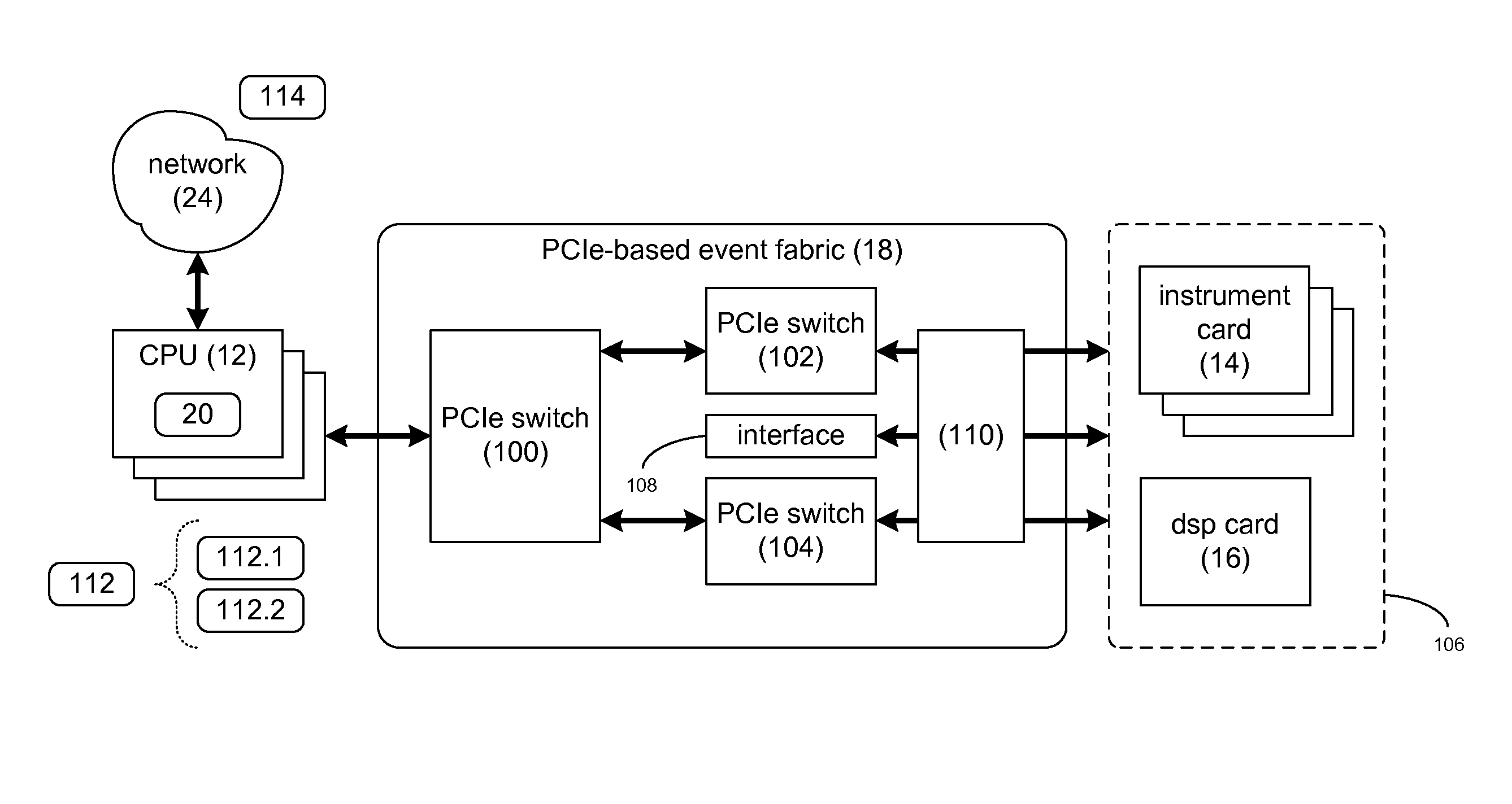
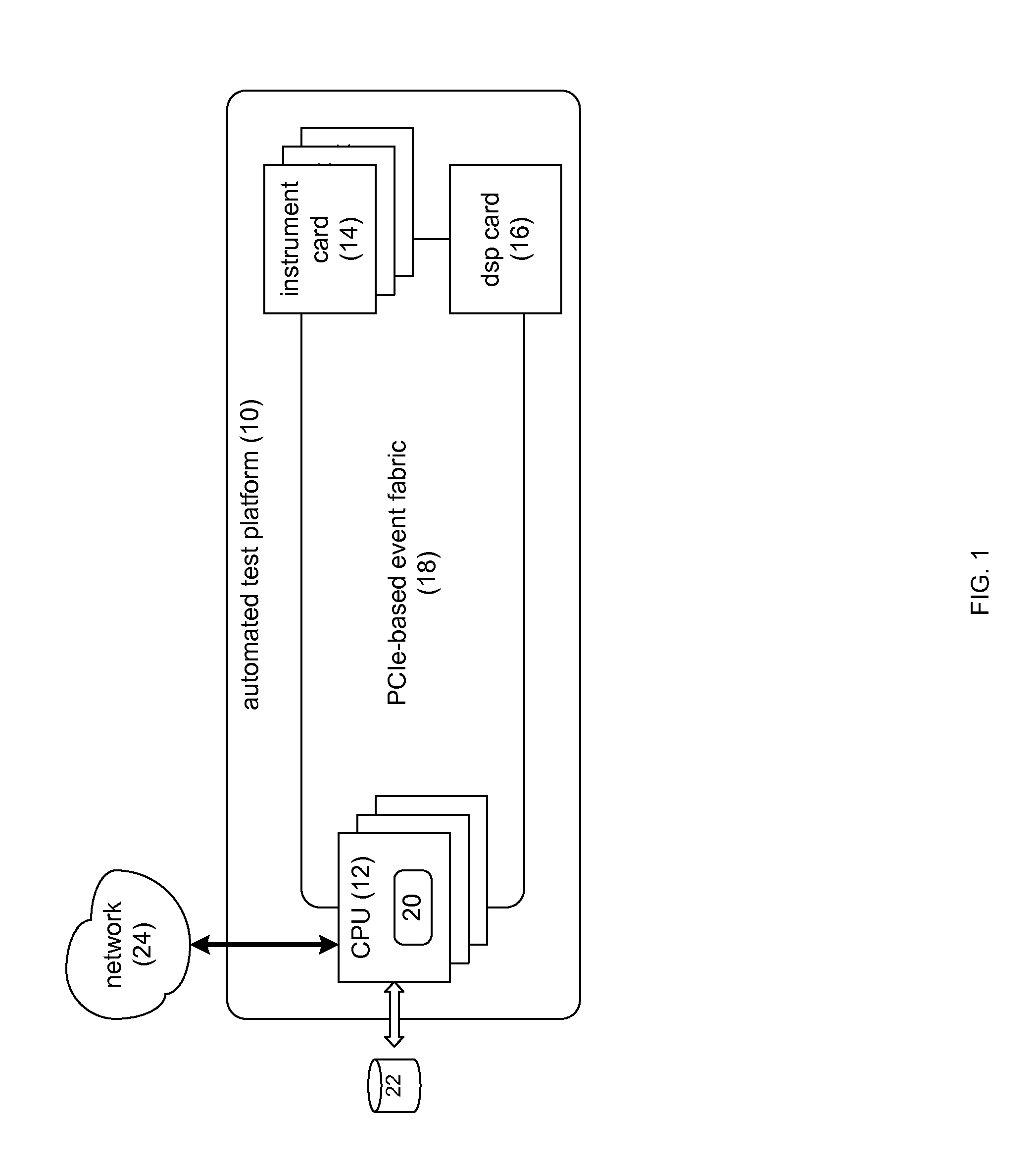
[0020]Referring to FIG. 1, there is shown automated test platform 10. Examples of automated test platform 10 may include, but are not limited to, systems that automate the verification and validation of devices under test (DUTs). As discussed above, automated test equipment systems (e.g. automated test platform 10) may be used to test various electronic components in an automated fashion. Typically, the devices under test are subjected to a battery of different tests, wherein the testing procedures are automated in a logical fashion. For example, during the testing of a power supply, the power supply may be subjected to varying voltage levels and varying voltage frequencies. Further, during the testing of a noise canceling circuit, such a circuit may be subjected to varying levels and frequencies of noise to confirm the satisfactory performance of the same.

[0021]Automated test platform 10 may include one or more central processing units (e.g. CPU subsystem 12), one or...


PUM


Abstract

A segmented subsystem, for use within an automated test platform, includes a first subsystem segment configured to execute one or more instructions within the first subsystem segment. A second subsystem segment is configured to execute one or more instructions within the second subsystem segment. The first subsystem segment includes: a first functionality, a second functionality, and a status polling engine. The status polling engine is configured to: determine a first status for the first functionality and a second status for the second functionality, and generate a consolidated status indicator for the first subsystem segment based, at least in part, upon the first status for the first functionality and the second status for the second functionality.

Description

TECHNICAL FIELD[0001]This disclosure relates to automated test equipment and, more particularly, to segmented automated test equipment.BACKGROUND[0002]Automated test equipment systems may be used to test various electronic components, which are often referred to as devices under test. Such systems may automate the testing of such components, wherein a component may be subjected to a battery of different tests in some form of logical fashion. Additionally, such systems may provide further levels of automation, wherein the components being tested are automatically swapped out (upon completion of a testing procedure) and replaced with a component that is yet to be tested. Unfortunately, such automated test equipment systems are often rigid in nature and proprietary in their design, resulting in systems that are not easily adaptable / scalable.SUMMARY OF DISCLOSURE[0003]In one implementation, a segmented subsystem, for use within an automated test platform, includes a first subsystem segm...

Claims


Application Information

Patent Timeline
IPC IPC(8): G06F9/30
CPCG06F11/2294G06F11/2733G06F11/273G06F9/30G06F9/30003
Inventor FRITZSCHE, WILLIAM A.POFFENBERGER, RUSSELL ELLIOTTPETROV, TODOR K.AMY, MICHAEL E.
Owner XCERRA
Why Eureka
Try Eureka