Elastic alignment assembly for aligning mated components and method of reducing postional variation

a technology of elastic alignment and assembly, which is applied in the direction of bolts, manufacturing tools, couplings, etc., can solve the problems of poor fit, undesirable effects, squeaking and rattling of mated components, etc., and achieve the effect of reducing the positional variation of a matable assembly and facilitating elastic deformation

Active Publication Date: 2014-07-31
GM GLOBAL TECH OPERATIONS LLC
View PDF7 Cites 36 Cited by
  • Summary
  • Abstract
  • Description
  • Claims
  • Application Information

AI Technical Summary

Benefits of technology

[0004]In another exemplary embodiment, a method of reducing positional variation of a matable assembly is provided. The method includes inserting at least one protrusion of a first component into at least one receiving feature of a second component, wherein the at least one protrusion comprises a protrusion width and the at least one receiving feature comprises a receiving feature width. The method also includes contacting a first sidewall and a second sidewall of the at least one protrusion with the at least one receiving feature. The method further includes elastically deforming at least one of the first sidewall and the second sidewall upon contacting the at least one receiving feature, wherein the elastic deforming is facilitated by a recess formed in the at least one protrusion between the first sidewall and the second sidewall. The method yet further includes performing an elastic averaging of the elastic deformation over the first sidewall and the second sidewall, wherein upon reaching a fully engaged position of the at least one protrusion a fitted alignment between the first component and the second component is established.

Problems solved by technology

As a result, occurrence of significant positional variation between the mated components, which contributes to the presence of undesirably large and varying gaps and otherwise poor fit, is possible.
Additional undesirable effects may include squeaking and rattling of the mated components, for example.

Method used


Image

  • Elastic alignment assembly for aligning mated components and method of reducing postional variation
  • Elastic alignment assembly for aligning mated components and method of reducing postional variation
  • Elastic alignment assembly for aligning mated components and method of reducing postional variation

Examples


Embodiment Construction

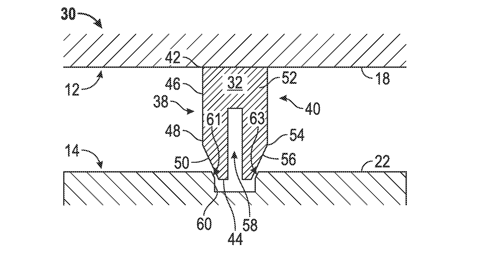
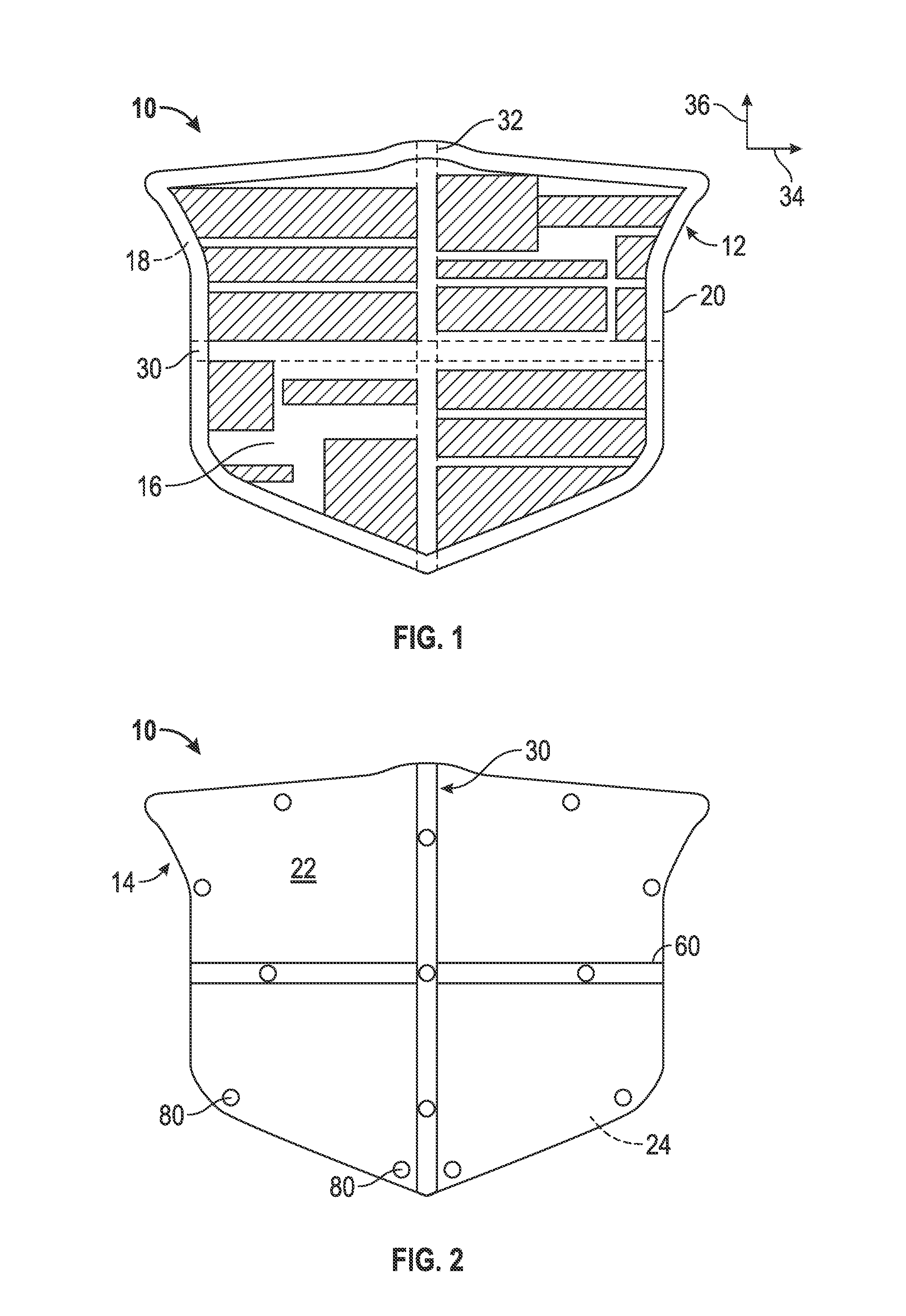
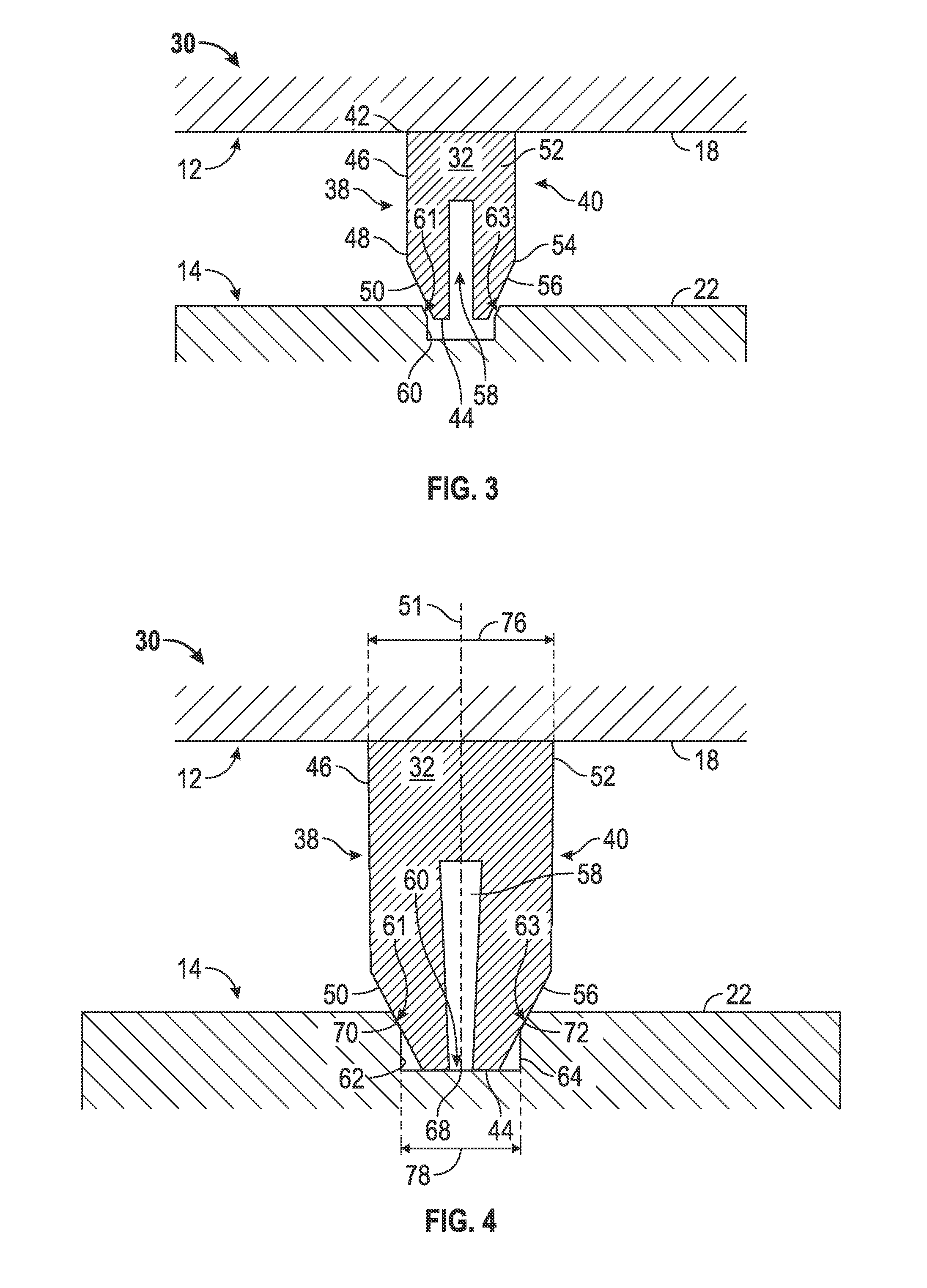
[0012]Referring to FIGS. 1 and 2, a matable assembly 10 is illustrated. The matable assembly 10 comprises matable components, such as a first component 12 and a second component 14 that may be disposed in a mated configuration with respect to each other. In one embodiment, the matable assembly is employed in a vehicle application, and comprises a vehicle feature such as a vehicle emblem. However, it is to be understood that the components may be associated with numerous other applications and industries, such as home appliance and aerospace applications, for example. In an exemplary embodiment such as a vehicle emblem for an automobile, the first component 12 comprises an emblem and the second component 14 comprises a bezel for receiving the emblem.

[0013]Although illustrated in a specific geometry, the first component 12 and the second component 14 may be configured in countless geometries. Irrespective of the precise geometry of the first component 12 and the second component 14, t...


PUM

PropertyMeasurementUnit
elasticaaaaaaaaaa
elastic alignmentaaaaaaaaaa
tapered angleaaaaaaaaaa

Abstract

An elastic alignment assembly includes a first component having a first engagement surface. Also included is a second component having a second engagement surface and is configured to be mated with the first component. Further included is a receiving feature formed in at least one of the first engagement surface and the second engagement surface. Yet further included is a protrusion comprising a first sidewall and a second sidewall, the protrusion extending away from at least one of the first engagement surface and the second engagement surface, the protrusion formed of an elastically deformable material to elastically deform at a first interface and a second interface upon contact with the receiving feature, wherein the first interface is located proximate the first sidewall and the receiving feature, and wherein the second interface is located proximate the second sidewall and the receiving feature.

Description

FIELD OF THE INVENTION[0001]The present invention relates to an elastic alignment assembly for aligning mated components, as well as a method of reducing positional variation for components of a matable assembly.BACKGROUND[0002]Currently, components which are to be mated together in a manufacturing process are subject to positional variation based on the mating arrangements between the components. One common arrangement includes components mutually located with respect to each other by 2-way and / or 4-way male alignment features; typically undersized structures which are received into corresponding oversized female alignment features, such as apertures in the form of holes and / or slots. Alternatively, adhesives or welding processes may be employed to mate parts. Irrespective of the precise mating method, there is a clearance between at least a portion of the alignment features which is predetermined to match anticipated size and positional variation tolerances of the mating features ...

Claims


Application Information

Patent Timeline
Patent Type & Authority Applications(United States)
IPC IPC(8): F16B1/00
CPCF16B1/0071B60R13/005F16B19/02Y10T29/4978Y10T403/20F16B2200/95
Inventor COLOMBO, JOELRICHARDSON, MICHAEL D.MORRIS, STEVEN E.
Owner GM GLOBAL TECH OPERATIONS LLC
Why Eureka
Try Eureka