
Method and apparatus for detecting an arc in a DC circuit

Active Publication Date: 2014-07-31
SMA SOLAR TECHNOLOGY
View PDF9 Cites 17 Cited by
  • Summary
  • Abstract
  • Description
  • Claims
  • Application Information

AI Technical Summary

Benefits of technology

The present patent provides a method for detecting circuits that have arcs, which can help to accurately identify those signals that may interfere with the circuit. The patent also discusses an apparatus that is insensitive to interference signals in order to detect arcs in circuits.

Problems solved by technology

In circuits, in particular in DC (direct current) circuits, in which high voltages occur in conjunction with high currents, there is a risk of an arc being formed.
In photovoltaic installations (referred to as PV installations in abbreviated form below), arcs are a problem which cannot be underestimated on account of the high DC voltage and the high prevailing direct currents and are one of the main causes of fires in PV installations.
One problem with such methods is that high-frequency interference signals can be incorrectly attributed to an arc, thus resulting in incorrect triggering of the apparatus for detecting arcs.
Possible sources of interference signals are, for example, high-frequency radio transmitters, arcs which briefly occur in the current collectors of electric trains or trams which travel past in the immediate vicinity of the system being monitored, or electrical or electronic devices having insufficient electromagnetic shielding or interference signal suppression.
Arcs in adjacent circuits may also couple into a system under consideration and may incorrectly trigger the apparatus for detecting arcs.
If, however, an interference signal has a frequency spectrum of a similar width to the typical frequency spectrum of an arc, this interference signal cannot be distinguished from a high-frequency signal originating from an arc.
However, in particular in circuits in which very high overall currents occur, for example in the DC circuits of PV installations, processes which trigger arcs cannot necessarily be clearly detected using a rate of change of the overall current.

Method used


Image

  • Method and apparatus for detecting an arc in a DC circuit
  • Method and apparatus for detecting an arc in a DC circuit
  • Method and apparatus for detecting an arc in a DC circuit

Examples


Embodiment Construction

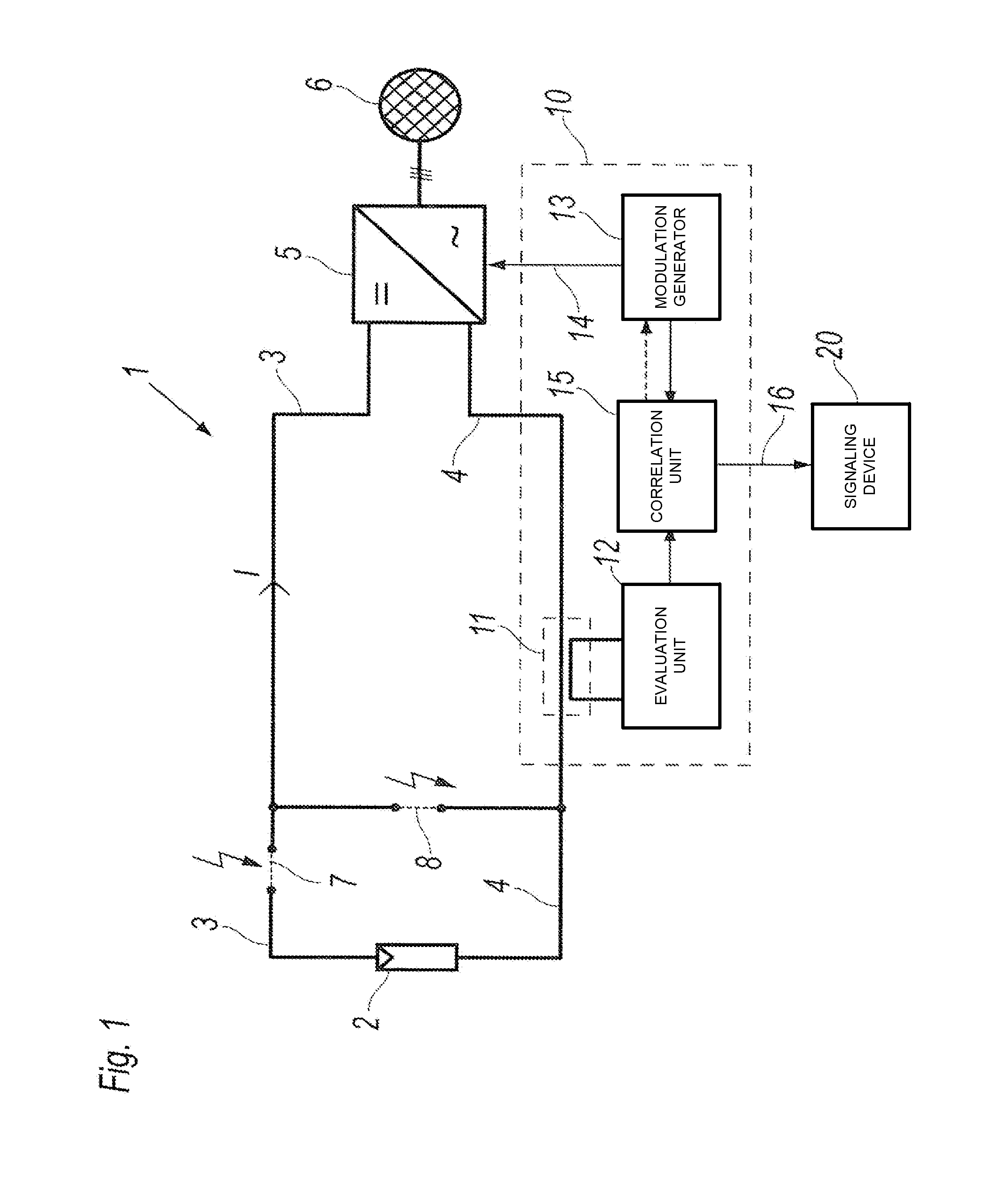
[0024]FIG. 1 schematically shows the basic structure of a PV installation 1 with an apparatus 10 for detecting an arc.

[0025]The PV installation 1 has a photovoltaic (PV) generator 2, from which direct current lines 3, 4 lead to a DC input stage of an inverter 5 which is connected to an energy supply grid 6.

[0026]By way of example, the PV generator 2 is symbolized in FIG. 1 by the circuit symbol for an individual photovoltaic cell. In one implementation of the PV installation illustrated, the PV generator 2 may be an individual photovoltaic (PV) module which in turn contains a multiplicity of photovoltaic cells. The PV generator 2 may likewise also be a series circuit comprising a plurality of PV modules, a so-called string. A parallel circuit or a mixed series and parallel circuit comprising PV modules are also possible.

[0027]The energy supply grid 6 may be a public supply system or a private system (isolated or island operation). For example, the inverter 5 is designed with three A...


PUM


Abstract

The disclosure relates to a method for detecting an arc in a DC circuit. The method includes measuring and analyzing an AC component (IAC) of a current (I) flowing in the circuit and determining at least one parameter of the AC component (IAC). The level of a DC component (IDC) of the current (I) is varied and a degree of correlation between the level of the DC component (IDC) of the current (I) flowing in the DC circuit and the at least one parameter of the AC component (IAC) is determined. An arc is detected and selectively signaled based on the degree of the determined correlation. The disclosure also relates to an apparatus for carrying out the method and to an inverter comprising such an apparatus.

Description

FIELD[0001]The disclosure relates to a method for detecting an arc in a DC circuit, in which a high-frequency signal in the circuit is measured and analyzed. The disclosure also relates to an apparatus for detecting arcs and to an inverter comprising such an apparatus.BACKGROUND[0002]In circuits, in particular in DC (direct current) circuits, in which high voltages occur in conjunction with high currents, there is a risk of an arc being formed. Arcs may occur, for example, during maintenance work (disconnection of a line through which current flows), in the event of degradation of contacts on screw connectors or plug-in connectors, at poor solder points or inadequately fastened screw connections or in the event of damaged line insulation. An arc which has been produced can usually only be extinguished by drastically reducing the current flowing via the arc.[0003]In photovoltaic installations (referred to as PV installations in abbreviated form below), arcs are a problem which cannot...

Claims


Application Information

Patent Timeline
IPC IPC(8): G01R31/02
CPCG01R31/025G01R31/54H02H1/0015H02H7/205G01R31/333H01H9/50H01H33/26H01H83/20
Inventor LANG, JOHANNESWEGENER, THOMASKRATOCHVIL, MARCELBEHRENDS, HOLGERVIOTTO, MICHAEL
Owner SMA SOLAR TECHNOLOGY
Learn More