Method, device and system for compensating brightness of a liquid crystal module
a liquid crystal module and brightness compensation technology, applied in static indicating devices, cathode-ray tube indicators, instruments, etc., can solve the problems of uneven light and dark appearance in the final product, waste a lot of manpower, financial and material resources without achieving the desired actual, and achieve the effect of improving the product yield
- Summary
- Abstract
- Description
- Claims
- Application Information
AI Technical Summary
Benefits of technology
Problems solved by technology
Method used
Image

Examples
embodiment 1
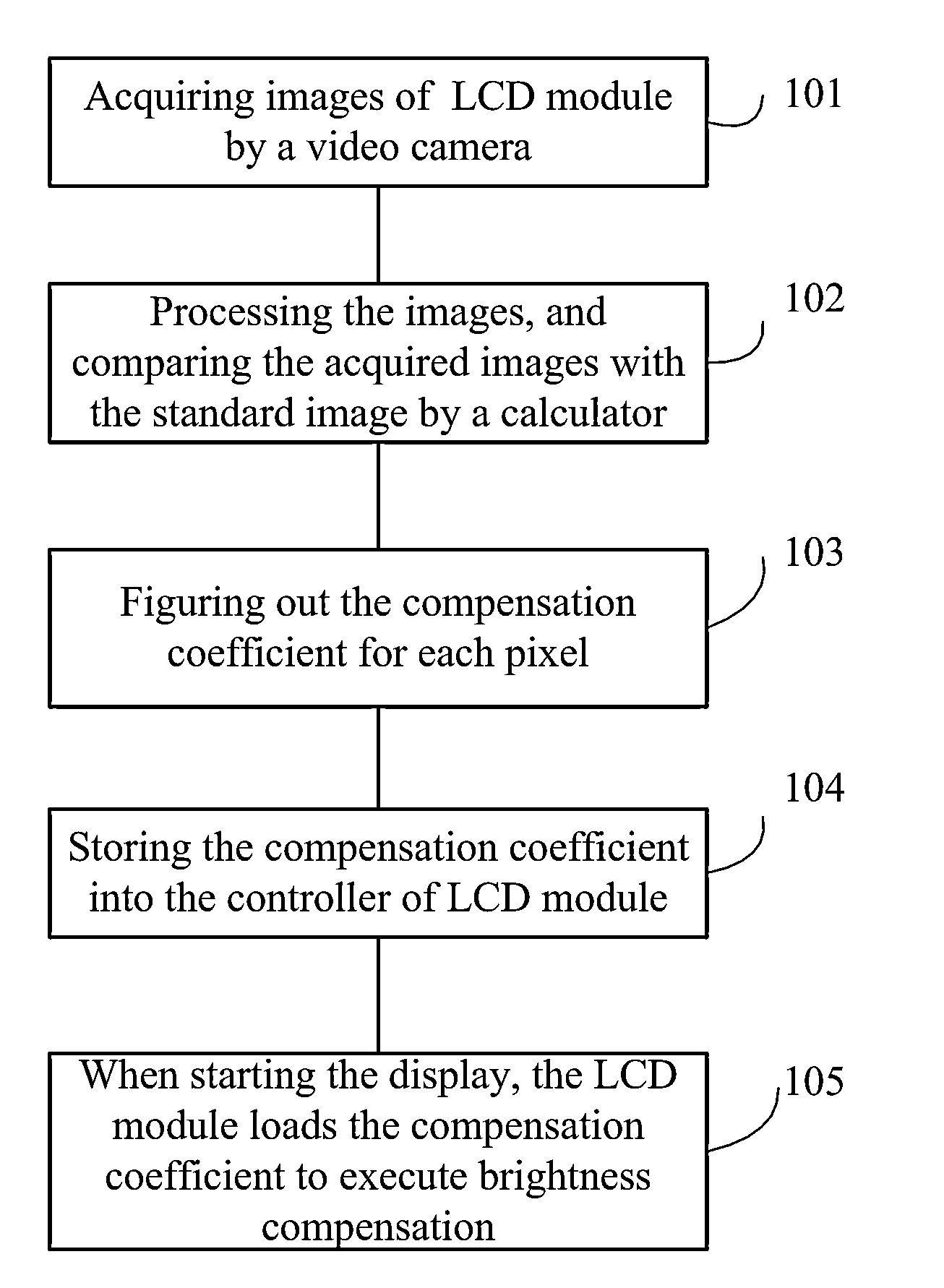
[0020]FIG. 1 is a flow chart of a method for compensating brightness of a LCM according to an embodiment of the present invention. In step 101, image acquiring is implemented to a liquid crystal module with scheduled image display to obtain the acquired image of the liquid crystal module. In step 102, the acquired image is compared with a standard image to find dark region. In step 103, the brightness difference between each pixel in the dark region and the corresponding pixel in the standard image is calculated to get compensation coefficients for each pixel in the dark region. In step 105, the compensation coefficients are stored into a display control circuit of the liquid crystal module. In step 105, When driving the liquid crystal module for display, the display control circuit compensates the backlight units corresponding to pixels in the dark region by using the compensation coefficients.
embodiment 2
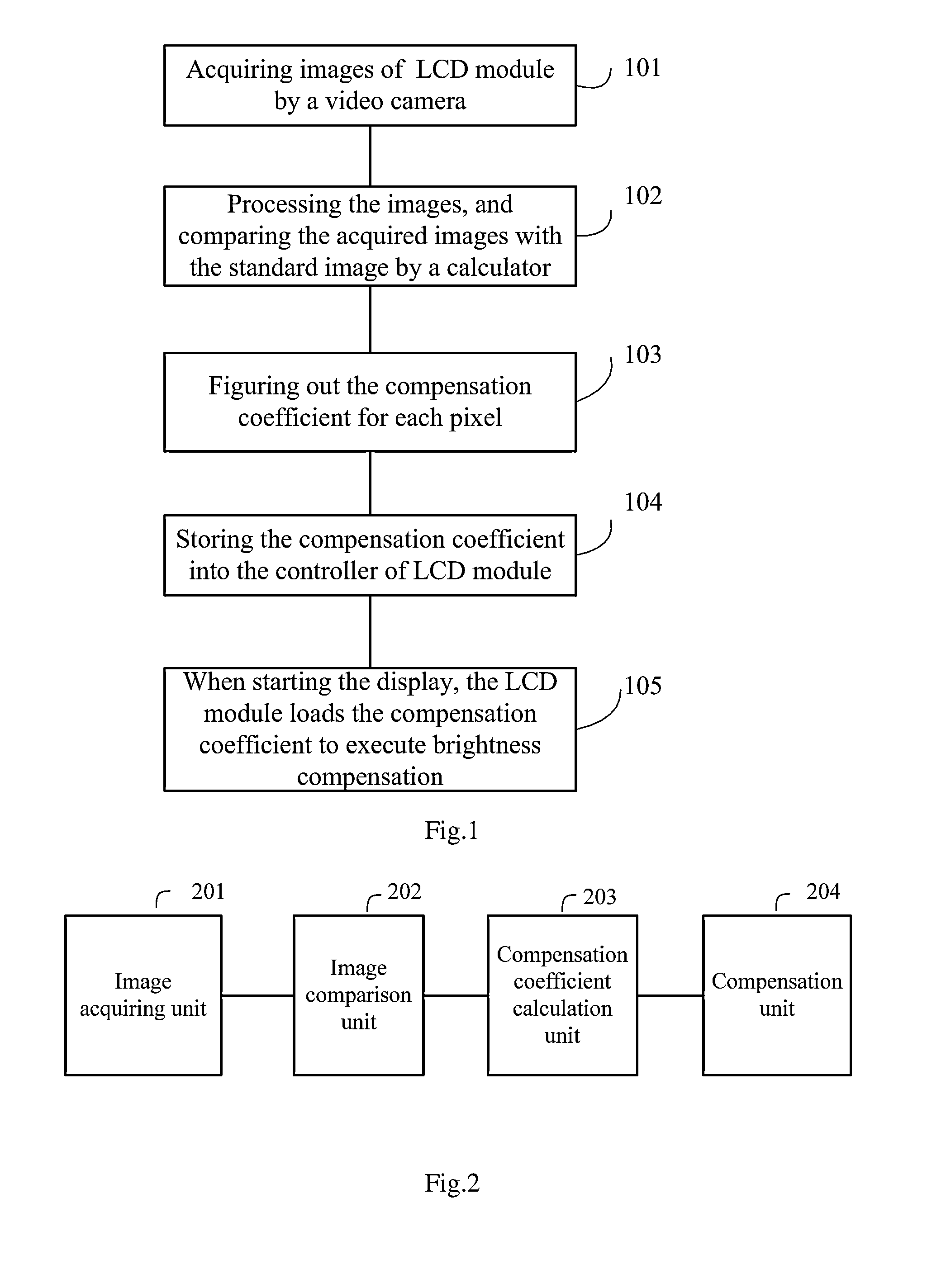
[0021]FIG. 2 is a block diagram of a device for compensating brightness of a LCM according to an embodiment of present invention. Compensating unit 200 shown in FIG. 2 includes an image acquiring unit 201 for acquiring image of liquid crystal module with scheduled image display to obtain the acquired image of the liquid crystal module. Also, the compensating unit 200 also includes an image comparing unit 202 for comparing the acquired image with a standard image to find dark region. The compensating unit 200 further includes a compensation coefficient calculating unit 203 for calculating the brightness difference between each pixel in the dark region and the corresponding pixel in the standard image to obtain compensation coefficients for each pixel in the dark region and storing the compensation coefficients into a display control circuit of the liquid crystal module. Additionally, the compensating unit 200 includes compensating unit 204 which is used for compensating the backlight...
embodiment 3
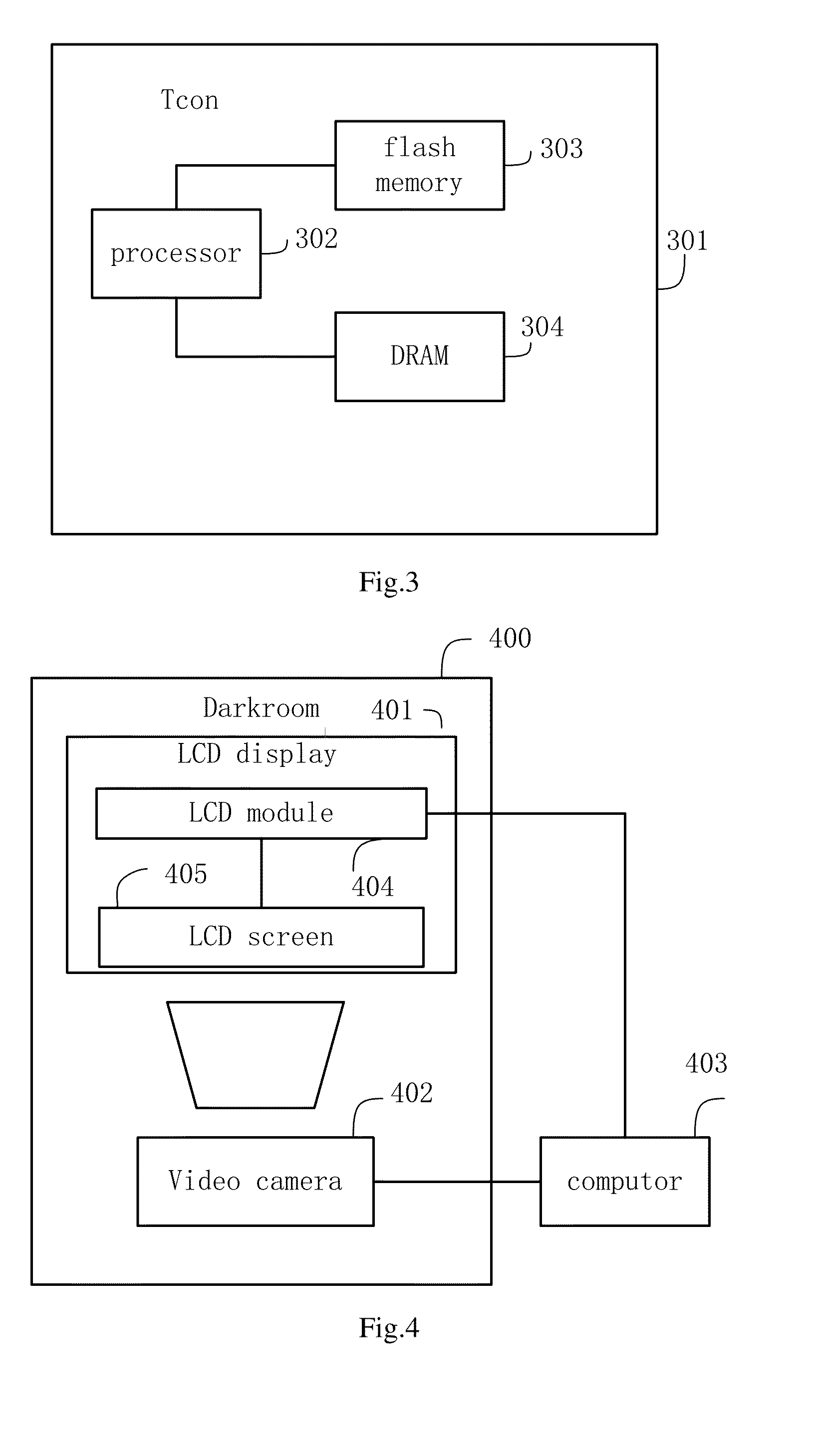
[0029]FIG. 4 is a block diagram of a system for compensating brightness of a LCM according to an embodiment of the present invention. Compensation system shown in FIG. 4 includes darkroom 400, LCM display 401, video camera 402 and COMPUTOR 403. Video camera 402 may be a camera with charge-coupled components. LCM display 401 includes LCM 404 and LCD screen 405. In the system, the LCM display 401 and video camera 402 are located in the darkroom 400, video camera 402 can be fixed in the darkroom and totally opposite to the LCD screen 405, so that the video camera 402 can just gather a whole display image of LCD screen 405 of LCM display 401. LCM 404 and video camera 402 are connected to COMPUTOR 406 respectively, so that the video camera 402 can transmit the acquired images to the COMPUTOR 403 for processing, and the COMPUTOR 403 can compensate LCM 404 according to the process result.
[0030]In an embodiment, one or more LCM displays 402 may be put in an assembly line. Images are acquire...
PUM
 Abstract
Description
Claims
Application Information
 - R&D
- Intellectual Property
- Life Sciences
- Materials
- Tech Scout
- Unparalleled Data Quality
- Higher Quality Content
- 60% Fewer Hallucinations
Browse by: Latest US Patents, China's latest patents, Technical Efficacy Thesaurus, Application Domain, Technology Topic, Popular Technical Reports.
© 2025 PatSnap. All rights reserved.Legal|Privacy policy|Modern Slavery Act Transparency Statement|Sitemap|About US| Contact US: help@patsnap.com