Lens having an extended range of focus and method of making the same

a technology of extended range of focus and lens, applied in the field of lenses, can solve the problems of strong radius curvature, and achieve the effects of large depth of field range, extended focus range, and good imaging quality

Active Publication Date: 2014-07-31
CARL ZEISS SMT GMBH
View PDF2 Cites 14 Cited by
  • Summary
  • Abstract
  • Description
  • Claims
  • Application Information

AI Technical Summary

Benefits of technology

[0012]It is an object of the invention to provide a novel lens with an extended range of focus. The novel lens should provide, either individually, in particular as an intraocular lens, or in conjunction with other optical components, optical systems which, while having a sufficiently good imaging quality, provide a large depth of field range. It should be possible to produce the novel lens in a cost-effective manner.

Problems solved by technology

In contrast to the monofocal IOLs, which were already introduced many years ago, multifocal lenses were previously only implemented for the bifocal case since there are significant problems in satisfying the aforementioned demands simultaneously.
A disadvantage in the case of intraocular lenses in particular is that a strong radius curvature is required when using “normal” spherical or aspherical basic lens shapes due to the relatively short focal length caused by the length of the eye.

Method used


Image

  • Lens having an extended range of focus and method of making the same
  • Lens having an extended range of focus and method of making the same
  • Lens having an extended range of focus and method of making the same

Examples


Embodiment Construction

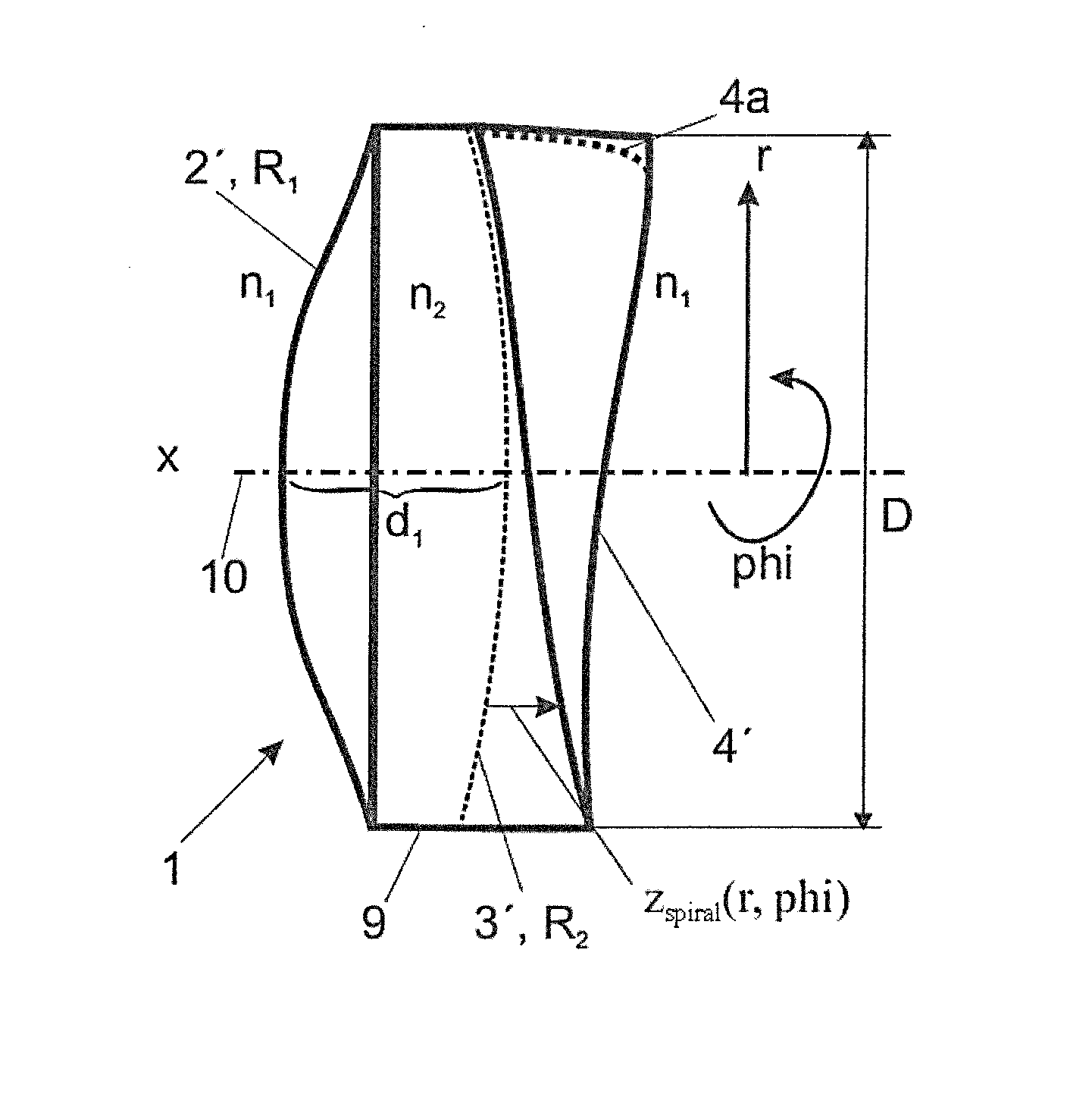
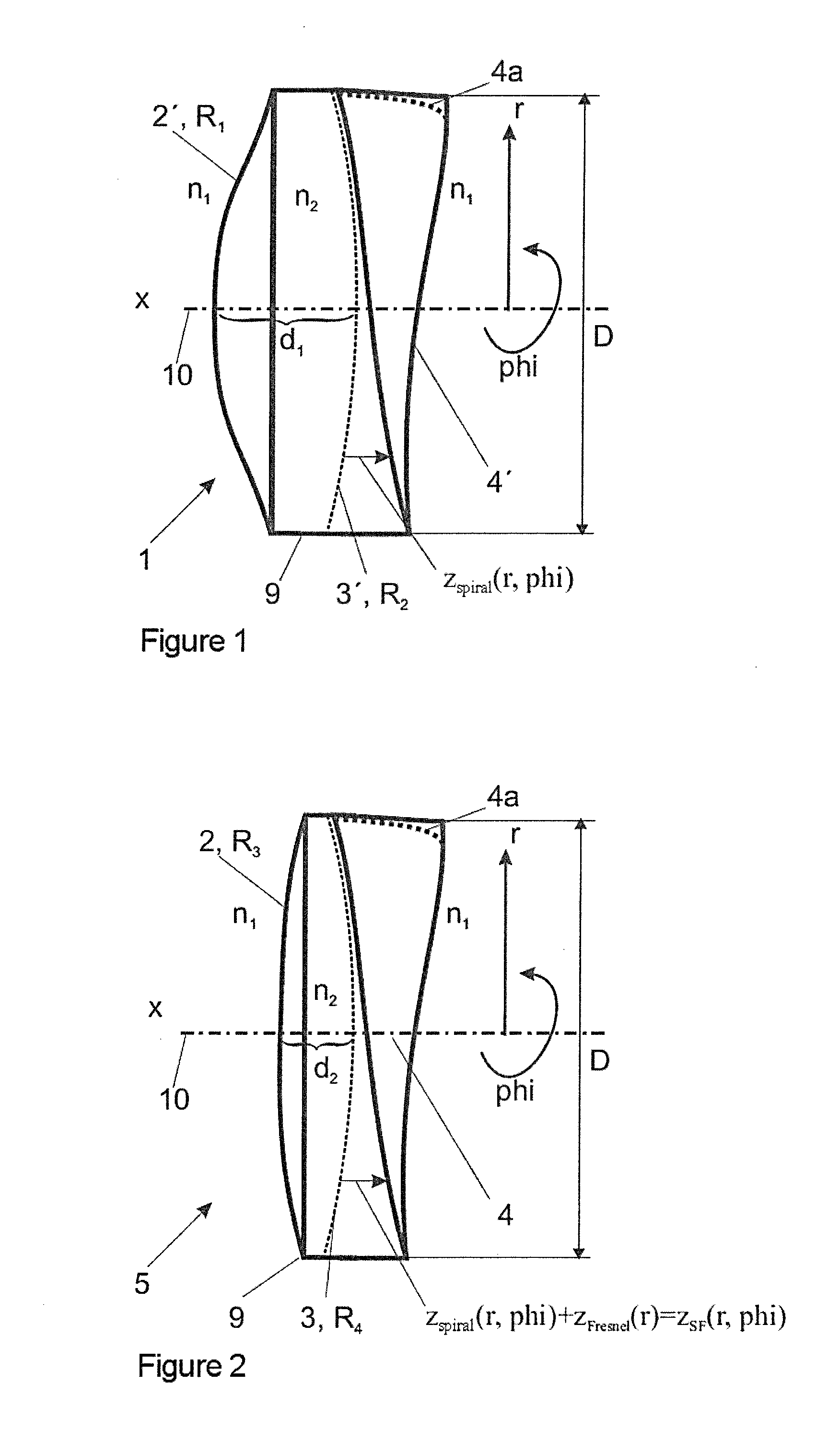
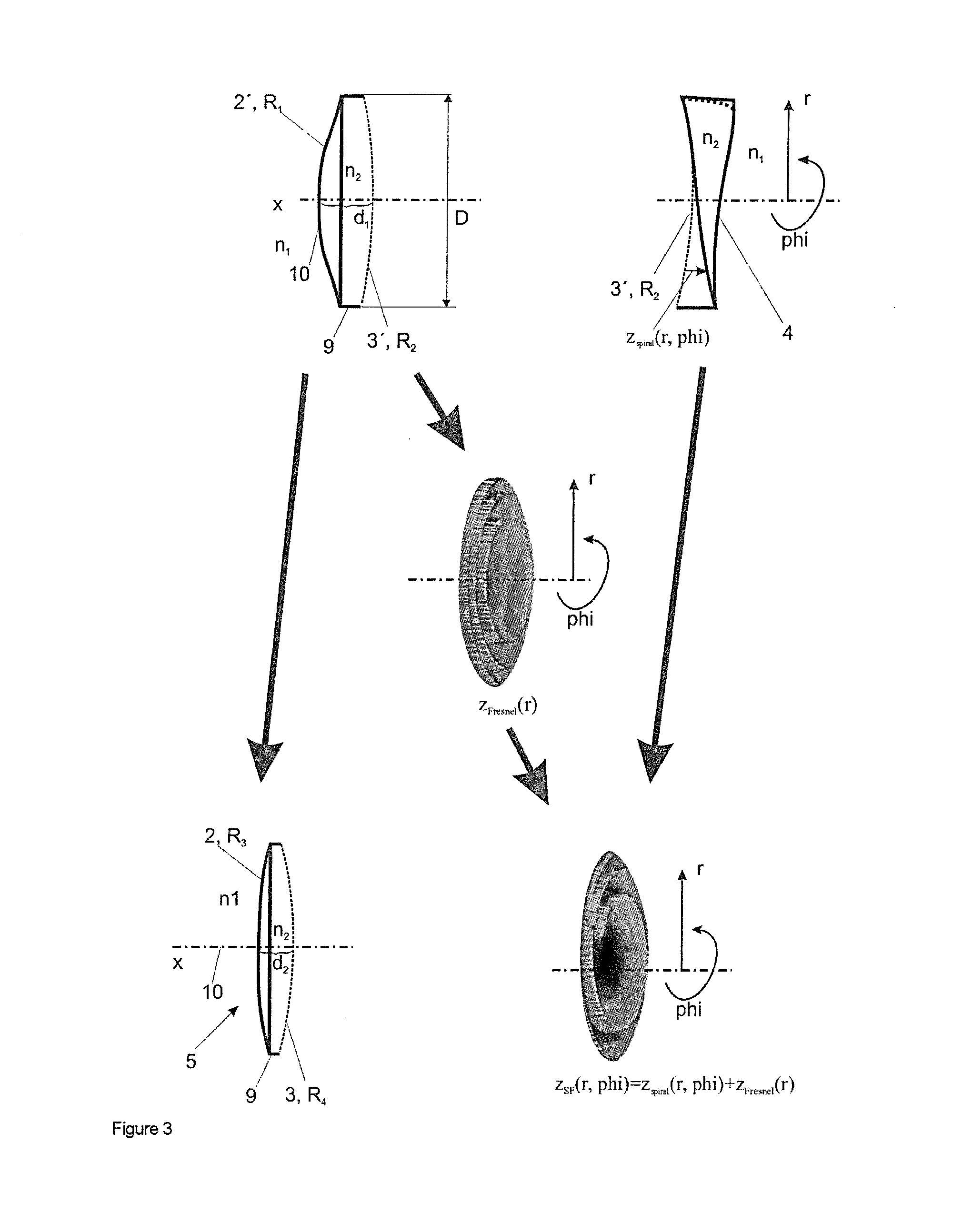
[0097]FIG. 1 shows a “thick” lens 1 having an extended range of focus as disclosed in DE 10 2011 101 899 A1, the content of which is incorporated by reference. Shown is a side view with a depiction of the spiral refractive height profile zspiral(r, phi), which produces the spiral focal power distribution Fspiral(r, phi). This lens 1 is initially determined by its base system with the radius R1 of the first optical surface 2′ and the radius R2 for the calculated base surface 3′, and also by the lens thickness d1 and the refractive index n2. These parameters are determined for an envisaged basic magnification. An additional material thickness z is “added” to the calculated shape of the base surface 3′ with the radius R2, with the additional material thickness being z=0 mm at phi=0, then increasing continuously and having a maximum value in the millimeter range at phi=2π. In practice, the maximum value will lie slightly in front of the azimuth angle phi=2π in order to realize a continu...


PUM


Abstract

A lens having an extended range of focus is made of a transparent material and has two optical surfaces. The lens defines an optical axis and a focal power distribution (Ftot) which, in relation to a plane perpendicular to the optical axis, changes as a function of the radial height (r) and of the azimuth angle (phi) of the aperture between a calculated basic value of the focal power (Flens) not equal to zero and a maximum value Fspiral max (r, phi).

Description

CROSS REFERENCE TO RELATED APPLICATIONS[0001]This application is a continuation application of international patent application PCT / EP2012 / 004026, filed Sep. 26, 2012, designating the United States and claiming priority from German application 10 2011 114 752.0, filed Sep. 29, 2011, and the entire content of both applications is incorporated herein by reference.FIELD OF THE INVENTION[0002]The invention relates to a lens which has an extended range of focus, wherein the lens consists of a solid material, the optical surfaces of the lens are transparent and the lens has a focal power distribution. The invention furthermore relates to a method for producing the lens and to the use thereof for influencing the imaging of an image onto the retina of an eye and to the use thereof in a lens system with an extended range of focus.BACKGROUND OF THE INVENTION[0003]Multifocal lenses should simultaneously meet a number of demands. Initially, a sufficiently good contrast transfer function in two ...

Claims


Application Information

Patent Timeline
Patent Type & Authority Applications(United States)
IPC IPC(8): G06F17/50G02B5/30G02B3/00
CPCG06F17/50G02B5/30G02B3/00G02B27/0075G02B5/1823G02B5/1842G02B5/1871G02C7/061A61F2/1618A61F2/1654G02C2202/20G02C7/022G06F30/00
Inventor DOBSCHAL, HANS-JUERGEN
Owner CARL ZEISS SMT GMBH
Why Eureka
Try Eureka