MRI DIFFUSION WEIGHTED IMAGING WITH ESTIMATED MOTION PROBING GRADIENT b-FACTORS BASED ON ACQUIRED APPARENT DIFFUSION COEFFICIENTS FOR EACH PIXEL

a diffusion weighted imaging and gradient technology, applied in the field of magnetic resonance diagnostic equipment and magnetic resonance diagnostic methods, can solve the problems of motion artifacts increasing, snr (signal-to-noise ratio) deteriorating, and the cost of increasing

Active Publication Date: 2014-07-31
TOSHIBA MEDICAL SYST CORP
View PDF14 Cites 4 Cited by
  • Summary
  • Abstract
  • Description
  • Claims
  • Application Information

AI Technical Summary

Problems solved by technology

However, if the time δ for applying MPG pulse is increased to increase the b-factor, the TE (echo time) becomes extended, thereby causing SNR (signal-to-noise ratio) to deteriorate and motion artifact to increase.
However, in order to increase maximum gradient magnetic field intensity G to obtain a large b-factor while maintaining a constant TE, it is necessary to improve the hardware performance of the gradient magnetic field system, which requires the cost to increase.

Method used


Image

  • MRI DIFFUSION WEIGHTED IMAGING WITH ESTIMATED MOTION PROBING GRADIENT b-FACTORS BASED ON ACQUIRED APPARENT DIFFUSION COEFFICIENTS FOR EACH PIXEL
  • MRI DIFFUSION WEIGHTED IMAGING WITH ESTIMATED MOTION PROBING GRADIENT b-FACTORS BASED ON ACQUIRED APPARENT DIFFUSION COEFFICIENTS FOR EACH PIXEL
  • MRI DIFFUSION WEIGHTED IMAGING WITH ESTIMATED MOTION PROBING GRADIENT b-FACTORS BASED ON ACQUIRED APPARENT DIFFUSION COEFFICIENTS FOR EACH PIXEL

Examples


first embodiment

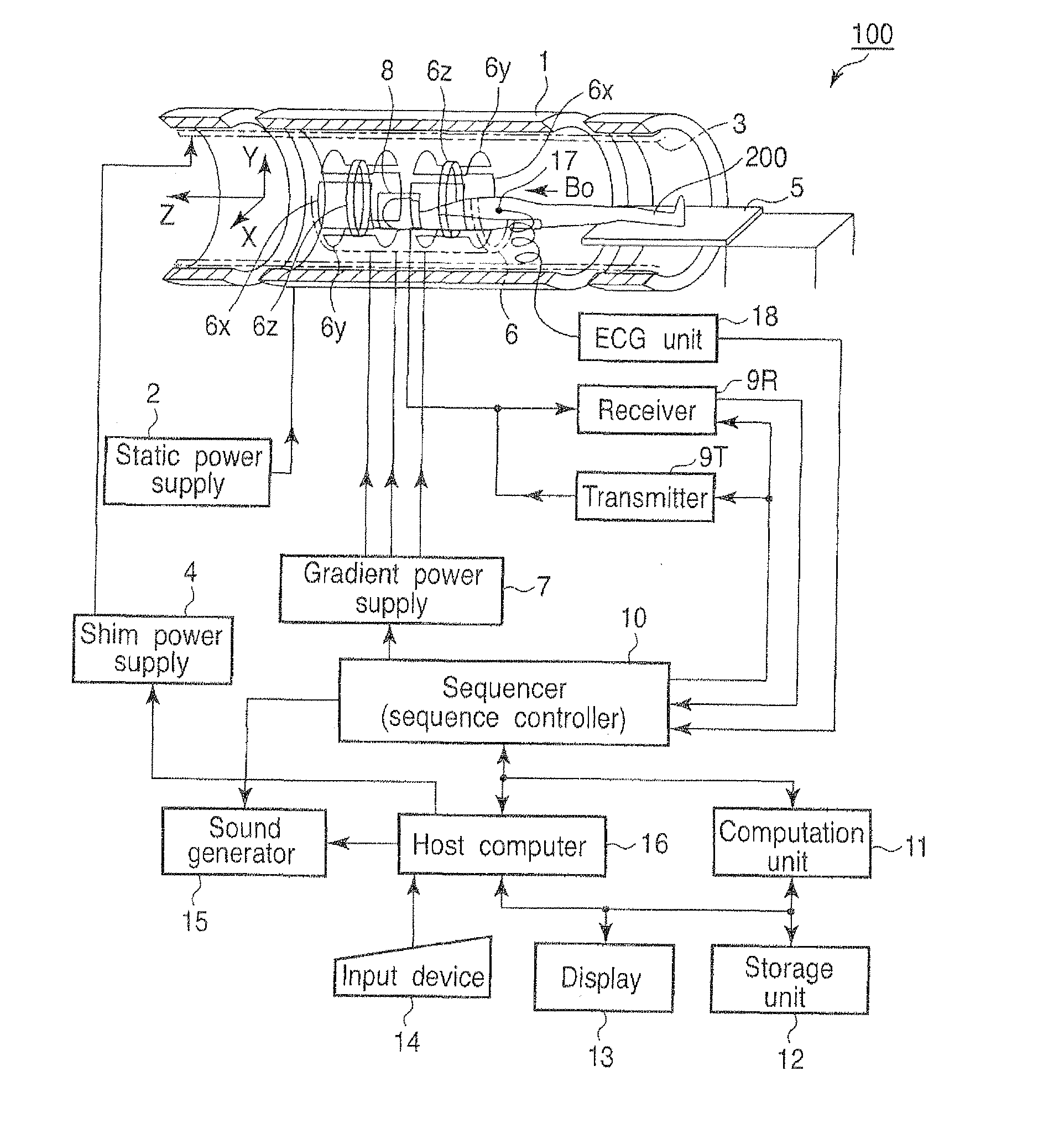
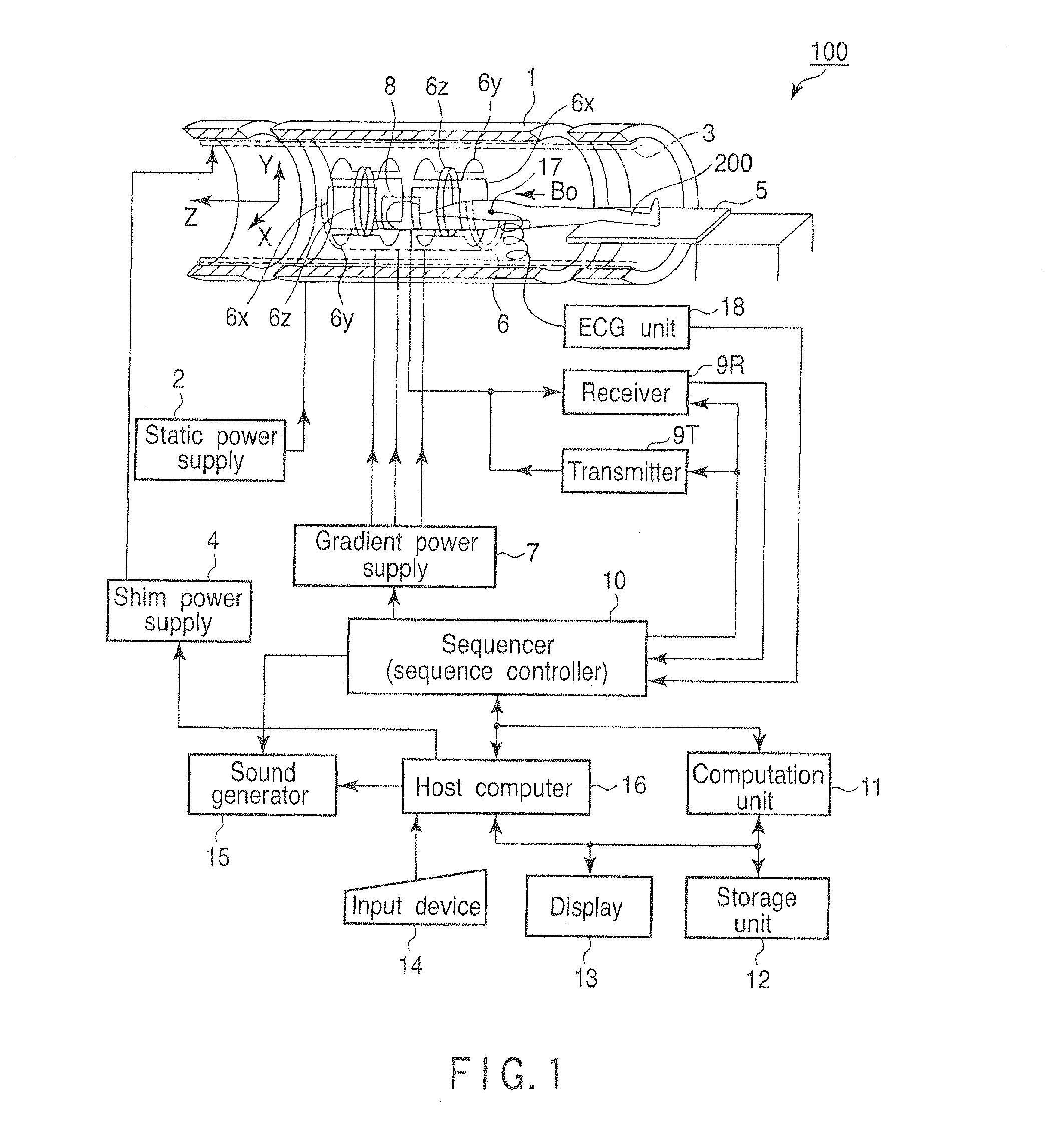
[0044]An operation carried out in a first embodiment of the magnetic resonance diagnostic apparatus 100 will be explained.

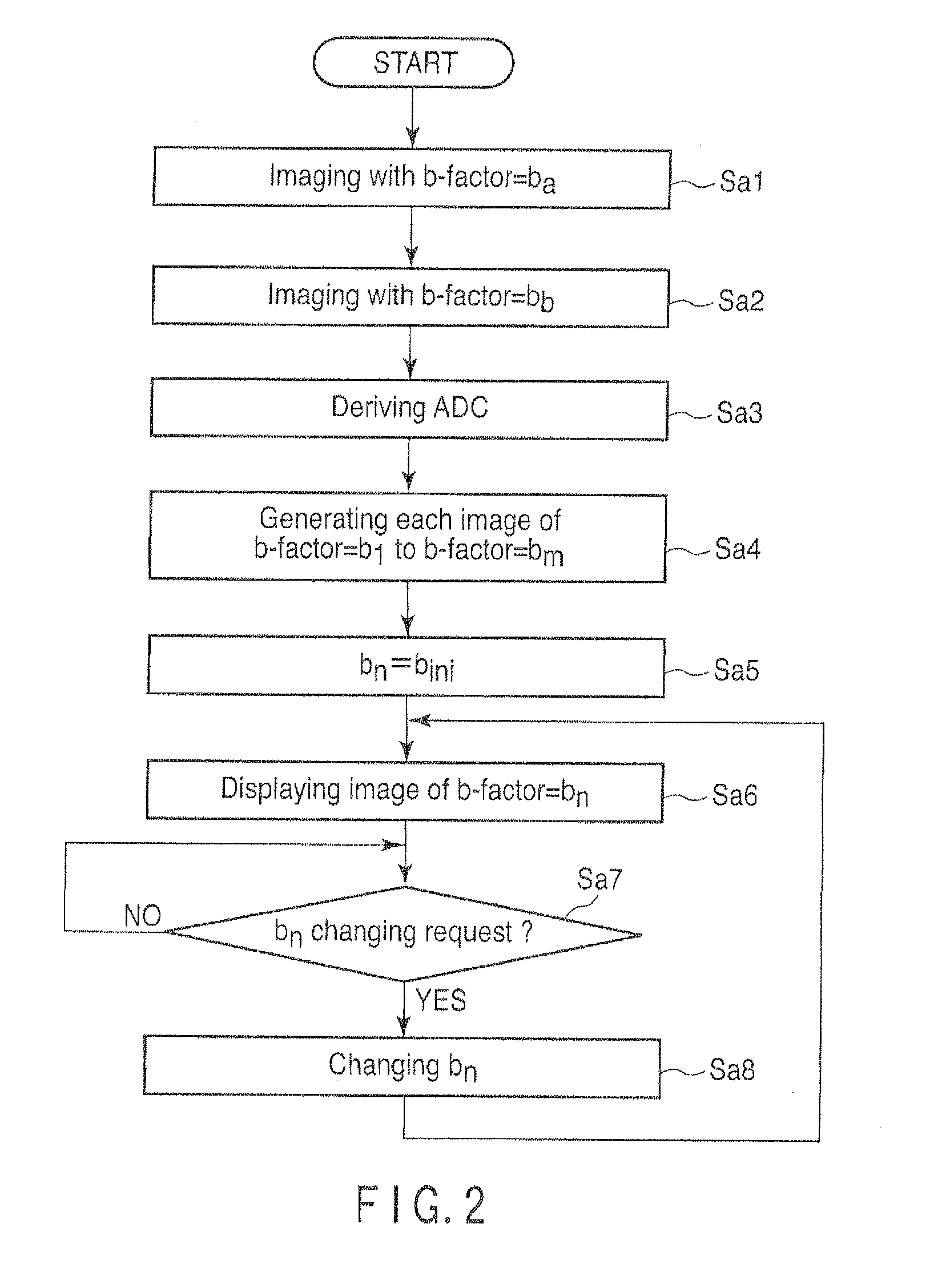
[0045]FIG. 2 is a flow chart showing a processing procedure in the first embodiment of the host computer 16.

[0046]In step Sa1, the host computer 16 instructs the sequencer 10 to carry out imaging in a predetermined region of interest, by setting a b-factor as a predetermined value ba. In accordance with this instruction, the sequencer 10 operates the gradient power supply 7, the transmitter 9T, the receiver 9R and the computation unit 11 etc., so as to carry out imaging by using a b-factor that has value ba. The image imaged here will be referred to as a first original image hereinafter.

[0047]Value ba can be an arbitrary value. However, 0 is preferable. In the case where ba=0, for imaging in step Sa1, it is fine to use T2 weighted imaging by a spin echo (SE) method or a fast spin echo (FSE) method. It is also fine to use imaging by a single-shot isotropic EPI met...

second embodiment

[0063]An operation in a second embodiment of the magnetic resonance diagnostic apparatus 100 will be explained.

[0064]FIG. 6 shows a flow chart illustrating a process procedure in the second embodiment of the host computer 16. Further, the same symbols are given for processes that are the same as those in FIG. 2, and explanations thereof will be omitted.

[0065]In step Sb1, the host computer 16 determines the part of the subject to become the target for imaging in the subsequent processes (hereinafter referred to as an imaging portion). The imaging portion can be determined in accordance with the user's assignment input via, for example, the input device 14.

[0066]In step Sb2, the host computer 16 instructs the sequencer 10 to carry out imaging with regard to a preset region of interest, by setting the b-factor as a setting value ba regarding an imaging portion. In accordance with this instruction, the sequencer 10 operates the gradient power supply 7, the transmitter 9T, the receiver 9...

third embodiment

[0081]The operation in a third embodiment of the magnetic resonance diagnostic apparatus 100 will be explained.

[0082]FIG. 8 is a flow chart showing the process procedure in the third embodiment of the host computer 16. Further, the same symbols are given for processes that are the same as in FIG. 2, and explanations thereof will be omitted.

[0083]Firstly, in step Sa1, the host computer 16 images the first original image in the same manner as in the first embodiment, then proceeds to step Sc1.

[0084]In step Sc1, the host computer 16 determines the imaging portion and acquires a diffusion coefficient D regarding the imaging portion thereof. A diffusion coefficient differs for each anatomy in the human body. Further, a standard diffusion coefficient in a normal tissue is already known. Therefore, an information table as shown in FIG. 9 that specifies the standard diffusion coefficient of an anatomy that may become the imaging portion is stored in the storage unit 12 in advance in associa...


PUM


Abstract

A magnetic resonance diagnostic apparatus includes a derivation unit to derive an apparent diffusion coefficient regarding a pixel position for each pixel position included in a region of interest in at least two original images obtained by imaging a same imaging region of a same subject using at least two b-factors that are different from each other, respectively, based on pixel values of each of at least two original images regarding the pixel positions, and a first estimation unit to estimate a pixel value obtained by using a b-factor that is different from the at least two b-factors, regarding each pixel position included in the region of interest, based on the apparent diffusion coefficient derived for each pixel position.

Description

CROSS-REFERENCE TO RELATED APPLICATIONS[0001]This is a division of U.S. Ser. No. 12 / 569,273 filed Sep. 29, 2009, which claims priority under 35 U.S.C. §119 based upon Japanese Patent Application No. 2008-251683 filed Sep. 29, 2008, and Japanese Patent Application No. 2009-167866 filed Jul. 16, 2009, the entire contents of all of which are incorporated herein by reference.BACKGROUND[0002]1. Technical Field[0003]The present exemplary embodiments are related to a magnetic resonance diagnostic apparatus and a magnetic resonance diagnostic method that use magnetic resonance phenomenon to obtain an image of a subject.[0004]2. Description of Related Art[0005]In diffusion weighted imaging (DWI), a pair of motion probing gradients (MPG) is added upon imaging. Further, a diffusion weighted image is obtained by imaging a signal difference that appears depending on the extent of phase diffusion of a spin of a proton transferred by diffusion while applying the MPG.[0006]As a value to indicate th...

Claims


Application Information

Patent Timeline
Patent Type & Authority Applications(United States)
IPC IPC(8): G01R33/56G06T11/00
CPCG06T11/003G01R33/5602A61B5/055A61B5/7285G01R33/543G01R33/56341
Inventor SUGIURA, SATOSHIKIMURA, TOKUNORIKAMATA, MITSUKAZU
Owner TOSHIBA MEDICAL SYST CORP
Why Eureka
Try Eureka