Flexible printed circuit as high voltage interconnect in battery modules

a printed circuit and high-voltage interconnection technology, applied in the direction of secondary cell servicing/maintenance, cell structural combination, cell components, etc., can solve the problems of high energy profile, high risk of wire breakage, and compromise operation or safety

Inactive Publication Date: 2014-07-31
TESLA INC
View PDF7 Cites 69 Cited by
  • Summary
  • Abstract
  • Description
  • Claims
  • Application Information

AI Technical Summary

Benefits of technology

[0011]Disclosed is a system and method for improving on conventional techniques for connecting energy storage elements of a high-voltage battery pack. The following summary of the invention is provided to facilitate an understanding of some of technical features related to use of a flexible printed circuit as a high-voltage current transfer medium in a battery pack, and is no

Problems solved by technology

These modular assembly techniques produce very dense energy profiles that can be susceptible to manufacturing and operational events that may compromise operation or safety.
However, conventional wire-bond techniques make the wire very susceptible to breaking whenever there is small amplitude relative motion between the collector plate and the end of the cell exposed in the aperture.
These disconnects produce current patterns in the collector plates that are difficult to model and assess accu

Method used


Image

  • Flexible printed circuit as high voltage interconnect in battery modules
  • Flexible printed circuit as high voltage interconnect in battery modules
  • Flexible printed circuit as high voltage interconnect in battery modules

Examples


Embodiment Construction

[0027]Embodiments of the present invention provide a system and method for improving on conventional techniques for connecting energy storage elements of a high-voltage battery pack. The following description is presented to enable one of ordinary skill in the art to make and use the invention and is provided in the context of a patent application and its requirements.

[0028]Various modifications to the preferred embodiment and the generic principles and features described herein will be readily apparent to those skilled in the art. Thus, the present invention is not intended to be limited to the embodiment shown but is to be accorded the widest scope consistent with the principles and features described herein.

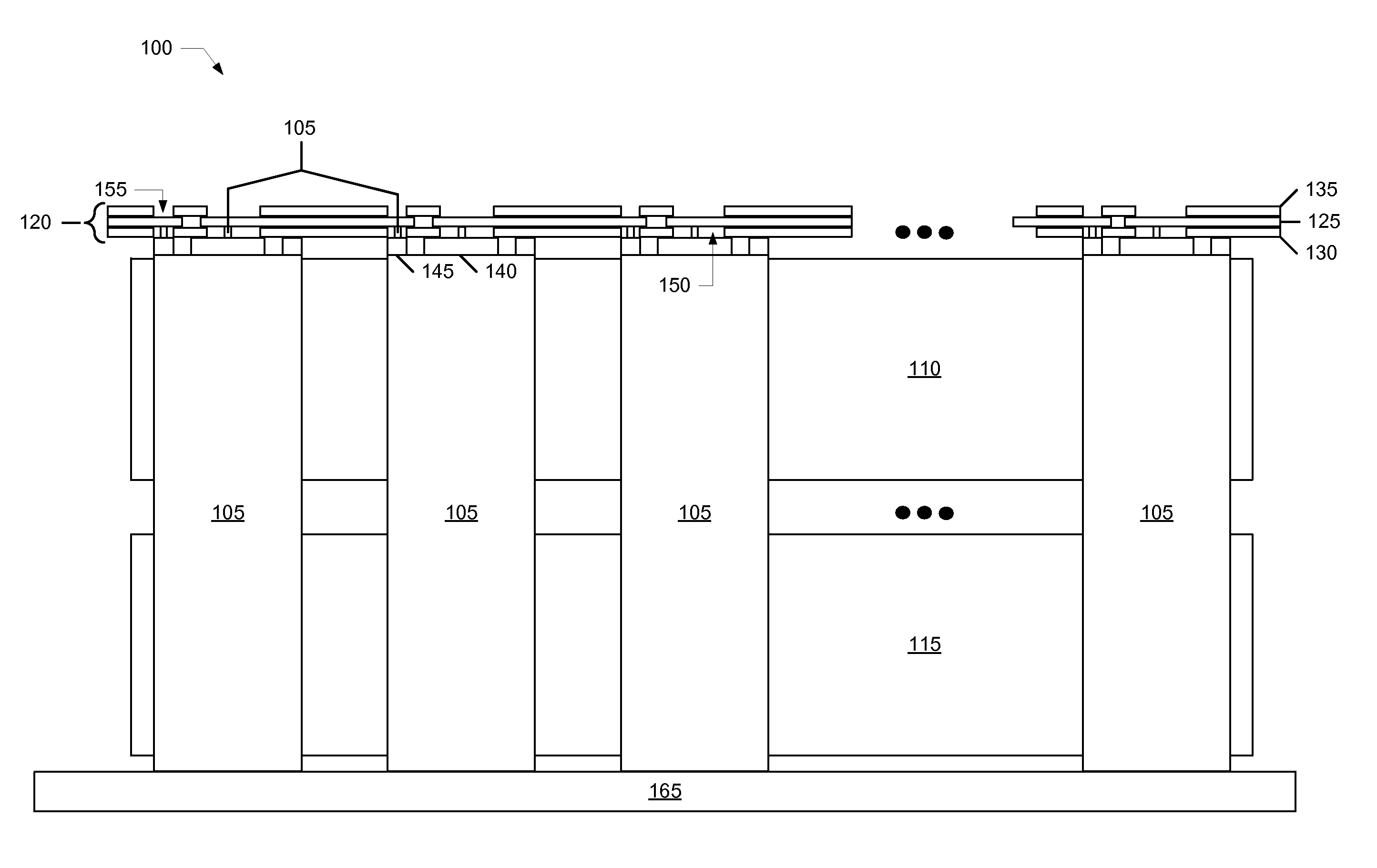
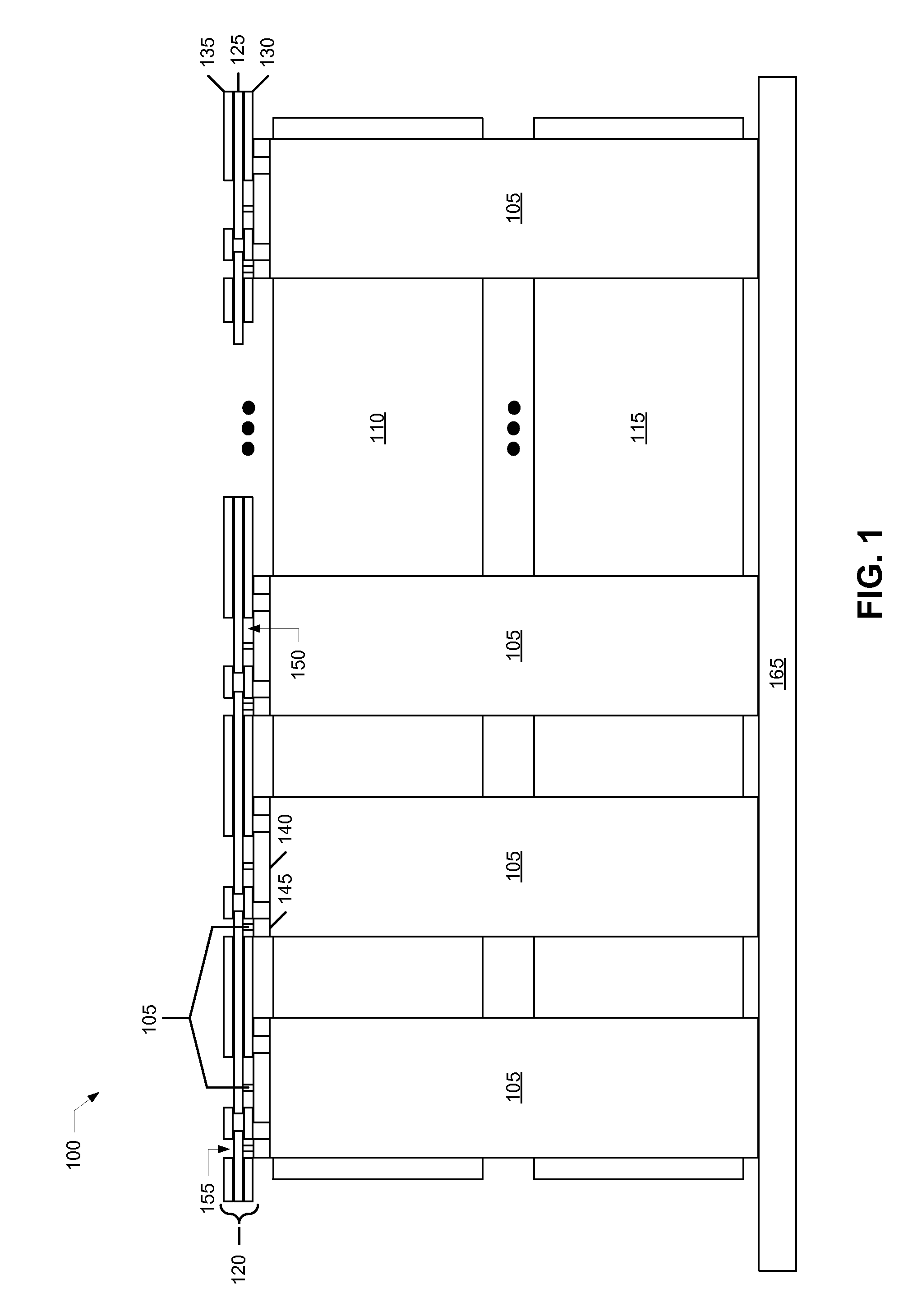
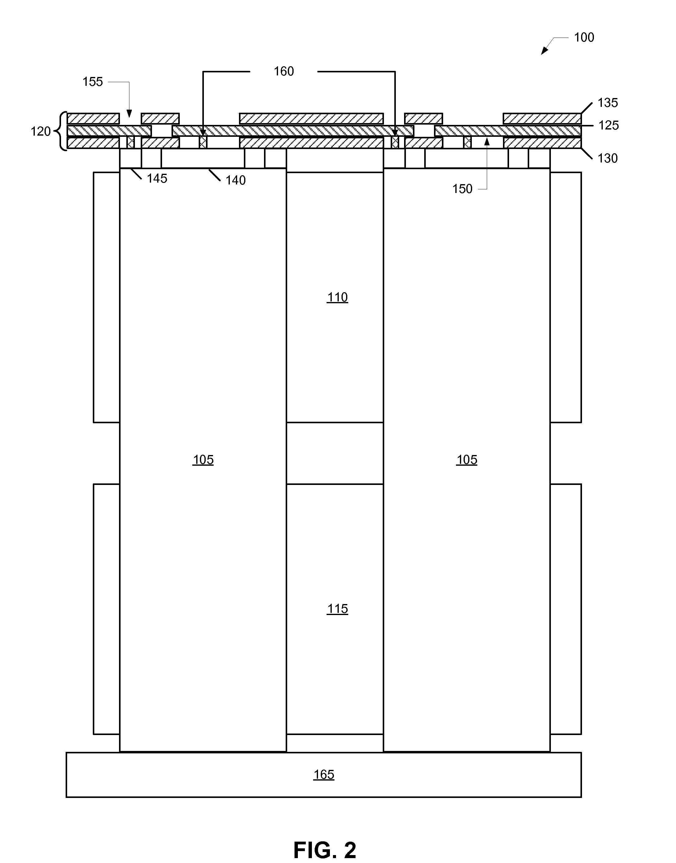
[0029]FIG. 1 illustrates a side view of an interconnected array 100 of energy storage elements 105. FIG. 2 illustrates a detail of a pair of energy storage elements 105. Elements 105 are physically secured and held in place by a pair of opposing clamshells—a top clamshell 110 ...


PUM


Abstract

A system and method for improving on conventional techniques for connecting energy storage elements of a high-voltage battery pack. A tuned flexible printed circuit individually coupled to each electrode of each cell of a matrix of cells of the battery pack provides improved manufacturability and reliability.

Description

FIELD OF THE INVENTION[0001]The present invention relates generally to high-voltage chargeable battery packs, and more specifically, but not exclusively, to high-voltage current connection of energy storage elements of the high-voltage chargeable battery packs.BACKGROUND OF THE INVENTION[0002]The subject matter discussed in the background section should not be assumed to be prior art merely as a result of its mention in the background section. Similarly, a problem mentioned in the background section or associated with the subject matter of the background section should not be assumed to have been previously recognized in the prior art. The subject matter in the background section merely represents different approaches, which in and of themselves may also be inventions.[0003]Battery packs, for purposes of this disclosure, include a plurality of series-connected battery elements. These elements may, in turn, include a parallel, series, or combination of both, collection of chargeable ...

Claims


Application Information

Patent Timeline
IPC IPC(8): H01M2/20H01M50/503H01M50/509H01M50/516H01M50/519H01M50/522
CPCH01M2/202H01M2/206H01M2/204H01M10/425H01M10/482H01M50/509H01M50/503H01M50/519H01M50/522H01M50/516Y02E60/10
Inventor LANE, ROBERT CLINTONWEINTRAUB, JEFF
Owner TESLA INC
Why Eureka
Try Eureka