Fluid dispensing device

a fluid delivery and fluid technology, applied in the field of fluid delivery devices, can solve the problems of inability method is a source of discomfort, and does not have the manual dexterity required to self-administer hypodermic injection, etc., and achieve the effect of easy detachable cartridge parts

Inactive Publication Date: 2014-07-31
ALPIMED
View PDF4 Cites 20 Cited by
  • Summary
  • Abstract
  • Description
  • Claims
  • Application Information

AI Technical Summary

Benefits of technology

[0016]A general aim of the invention is therefore to provide an improved fluid delivery device with easily detachable cartridge portion.

Problems solved by technology

Though effective, this method is a source of discomfort for patients requiring repeated injections over an extended period, for example diabetes patients.
Moreover a number of patients, in particularly elderly, visual-impaired, or patients suffering from arthritis, do not have the manual dexterity required to self-administer a hypodermic injection.
Unfortunately this is not always possible, even with the best injection technique.
These pens are easier to use than conventional syringes, yet they still require a certain amount of dexterity and force, and some patients find their use difficult.
Moreover, feedback about the proper operation of the system, about status, etc, is not provided.
Another shortcoming of the devices illustrated above, and of automatic-actuated syringes in general, is in their inconvenient size that compounds the dimensions of cartridge, plunger and actuator.

Method used


Image

  • Fluid dispensing device
  • Fluid dispensing device
  • Fluid dispensing device

Examples


case 1

Coil to Inner Coil Power Transfer

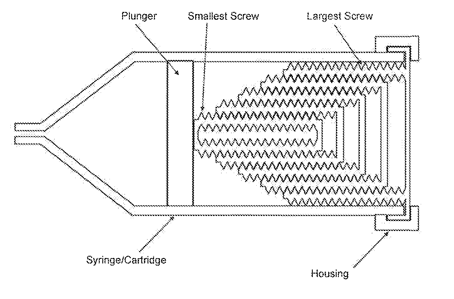
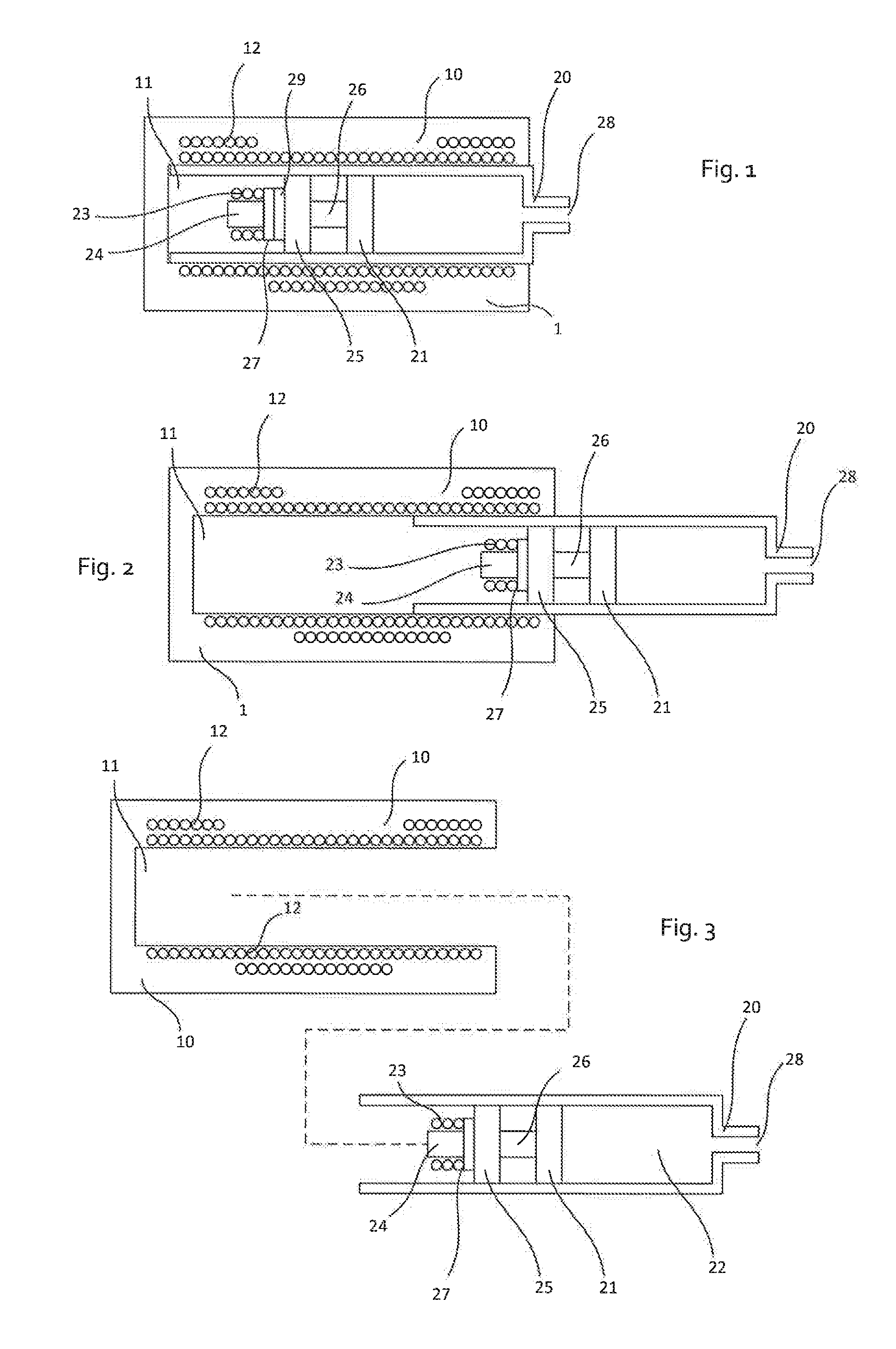
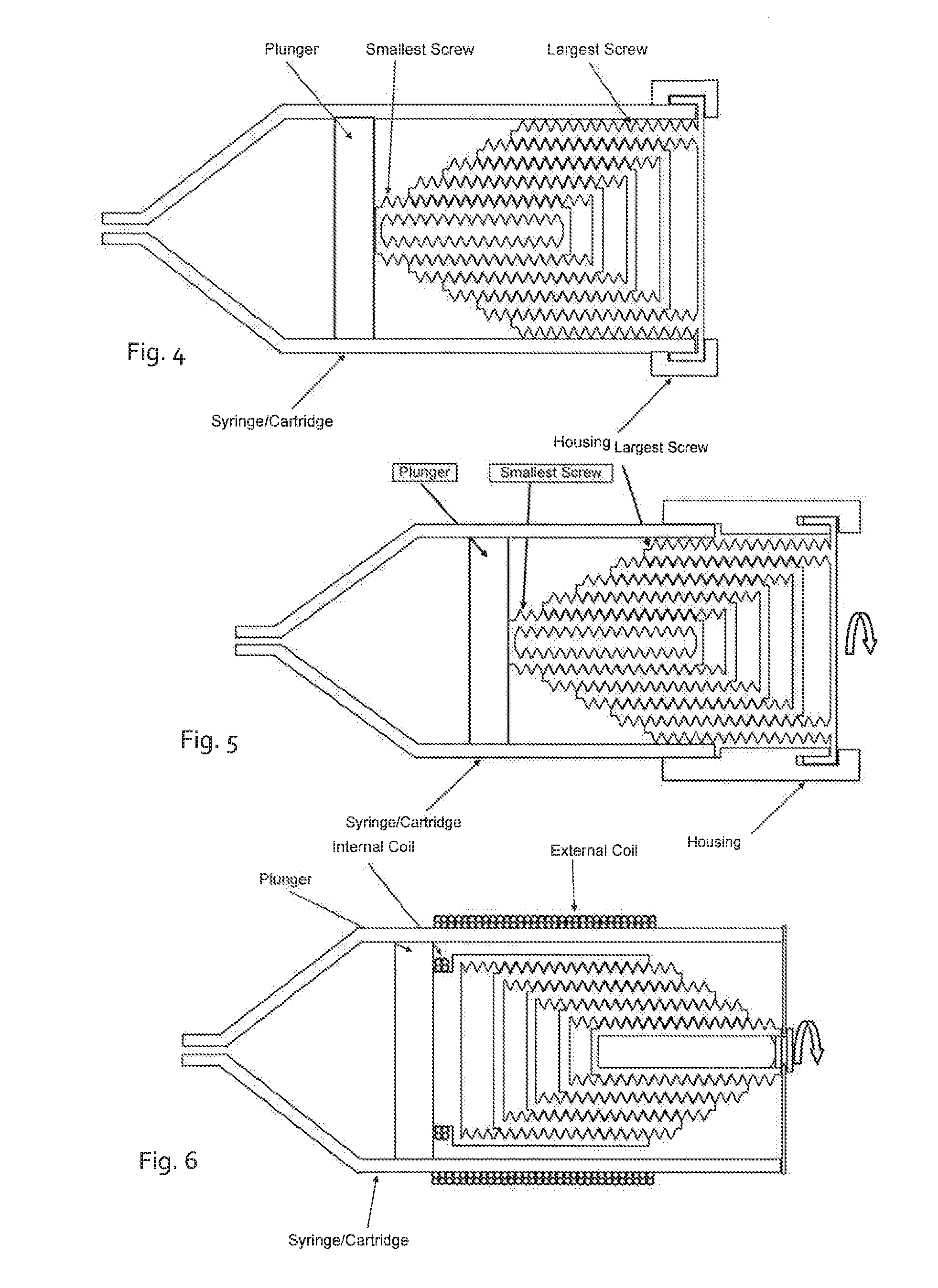
[0067]The outer coil 12 inductively transfers power to the inner coil 23, which energizes the piezoelectric actuator 25. The coil assembly, provided with outer coil 12 and inner coil 23, provides a transformer allowing the required voltage increase to drive the piezoelectric elements. When the proper signal sequence on the outer coil is provided, a linear stepwise movement of the piezoelectric actuator is generated, thereby causing a linear stepwise movement of the plunger 21.

case 2

Coil to Inner Coil Actuation Commands Transmission

[0068]According to this embodiment, the cartridge includes an energy source 29, for example an electrochemical battery or an accumulator. External coil 12 is used to transmit inductively actuation commands to the actuator 25 through the inner coil 23. For example, the actuator could receive inductively commands to start or stop motion of the plunger at a given speed, or to advance or retract the plunger by a given number of steps, or by a given distance, according to the implementation. In a variant, the energy source may be a rechargeable accumulator or a capacitor that can be recharged inductively by coils 12 and 23, for example during the periods of inactivity of the device. For simplicity's sake the energy source 29 is represented in FIG. 1 only.

case 3

Coil—Outer Coil Bidirectional or Unidirectional Data Transfer

[0069]The PCB electronics 27 contains a data transfer circuit, such as RFID circuit, allowing data transfer to the outer coil 12. The cartridge data may be contained in specific data storage element or within the piezoelectric driving or controlling electronics 27. Data may be static non-erasable data written during manufacturing, such as the medication details, expiry date, concentration, maximum daily dosage, manufacturer data, exact injection volume at each step, and the like. The transferred data can also be related to the movement of the piezoelectric assembly such as the discharge and charge times of the piezoelectric elements. Such movement indication gives information about the smoothness of the movement, which can be used to detect any blockage in the fluid path or the eventual formation of bubbles.

[0070]The use of the outer coil assembly as a data transfer interface constitutes an independent aspect of the invent...


PUM


Abstract

A device for delivering fluid, comprising an elongated outer casing (10) provided with a substantially cylindrical inner chamber (11); a plunger (21) movable axially along a longitudinal axis A-A of an inner reservoir (22) towards an outlet (28); an actuator comprising a multi-stage lead-screw with a plurality of coaxial, screwably-interconnected bushings and an output spindle or an output bushing linked to the movable plunger (21), whereby a rotation of the rotating element causes a translation of the bushings relative to each other in telescopic fashion, and a translation of the movable plunger in the cartridge.

Description

REFERENCE DATA[0001]The present application claims priority from Swiss patent application CH0379 / 13 of Jan. 31, 2013, the contents whereof are incorporated by reference.FIELD OF THE INVENTION[0002]The present invention relates to a device for delivering fluid, comprising an elongated outer casing provided with a substantially cylindrical inner chamber, and an inner cartridge for insertion into said inner chamber. The cartridge comprises a plunger movable axially along a longitudinal axis of an inner reservoir towards an outlet. The device also comprises a coil assembly. The invention also relates to the corresponding method for delivering fluid from a cartridge.[0003]Some embodiments of the present invention relate to a device for administering pharmaceutical drugs by injection or infusion, yet the invention is not limited to this application and could also serve to deliver precisely metered amounts of adhesives, lubricants, solder pastes, chemical reagents, or any other fluid in al...

Claims


Application Information

Patent Timeline
Patent Type & Authority Applications(United States)
IPC IPC(8): A61M5/20A61M5/315
CPCA61M5/31585A61M5/2033A61M5/31511A61M2005/31518A61M2205/0266A61M2205/0294A61M2205/6018A61M2205/8243
Inventor MORTAZAVI, BEHZAD
Owner ALPIMED
Why Eureka
Try Eureka