Measuring differential group delay in an optical fiber connection

Active Publication Date: 2010-06-03
FRANCE TELECOM SA
View PDF21 Cites 18 Cited by
  • Summary
  • Abstract
  • Description
  • Claims
  • Application Information

AI Technical Summary

Benefits of technology

[0047]When the optical fiber connection carries a wavelength division multiplexed (WDM) signal, the measuring system can include a tunable filter for selecting a wavelength in the connection. The tunable filter can be connected through an optical amplifier to a monitoring port for any element of the optical connection. For instance, th

Problems solved by technology

In an optical fiber transmission system, the whole connection, including line fiber sections and chromatic dispersion compensation fiber sections, as well as various elements of the system, such as multiplexers, demultiplexers, amplifiers, and OADM (Op

Method used


Image

  • Measuring differential group delay in an optical fiber connection
  • Measuring differential group delay in an optical fiber connection
  • Measuring differential group delay in an optical fiber connection

Examples


Embodiment Construction

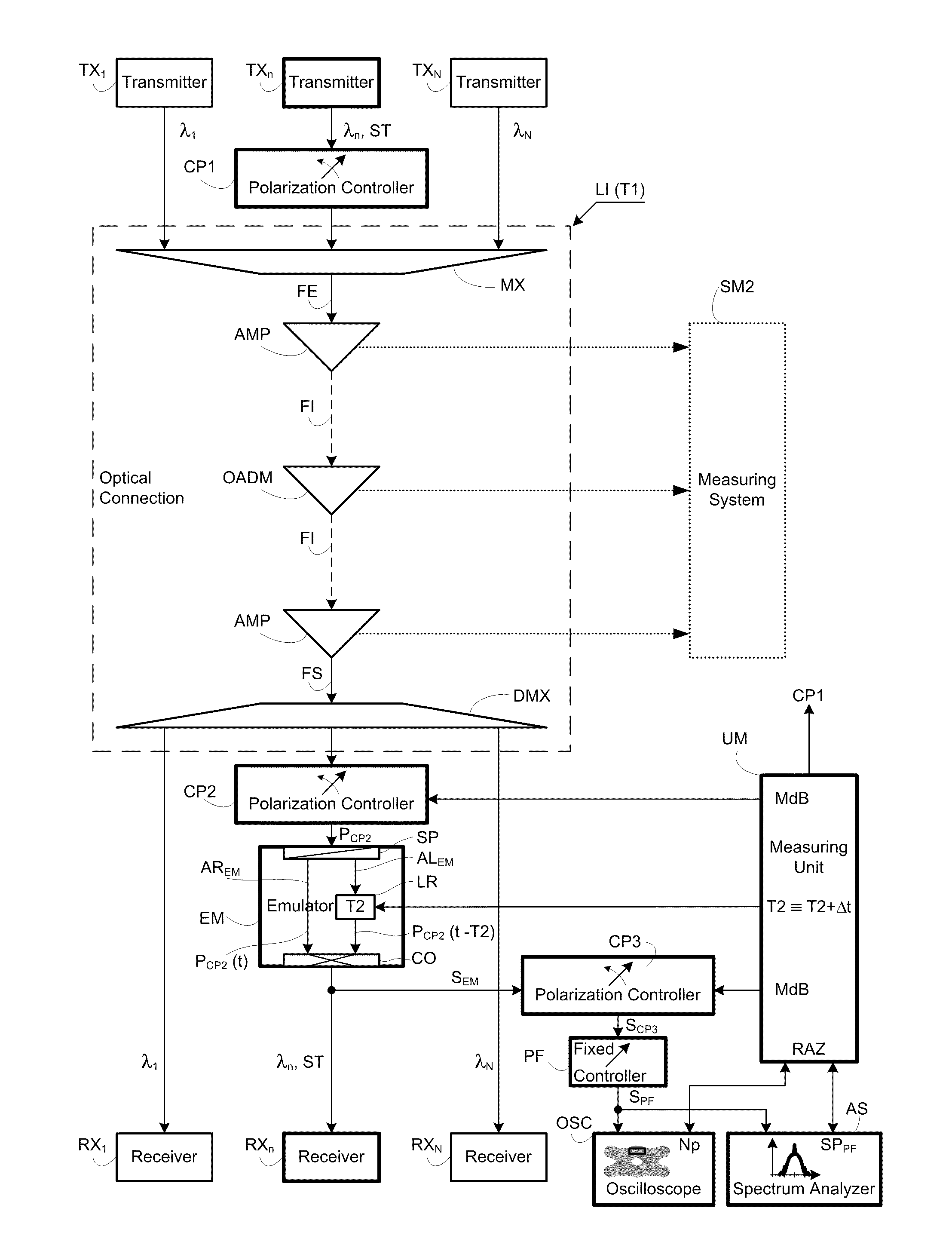
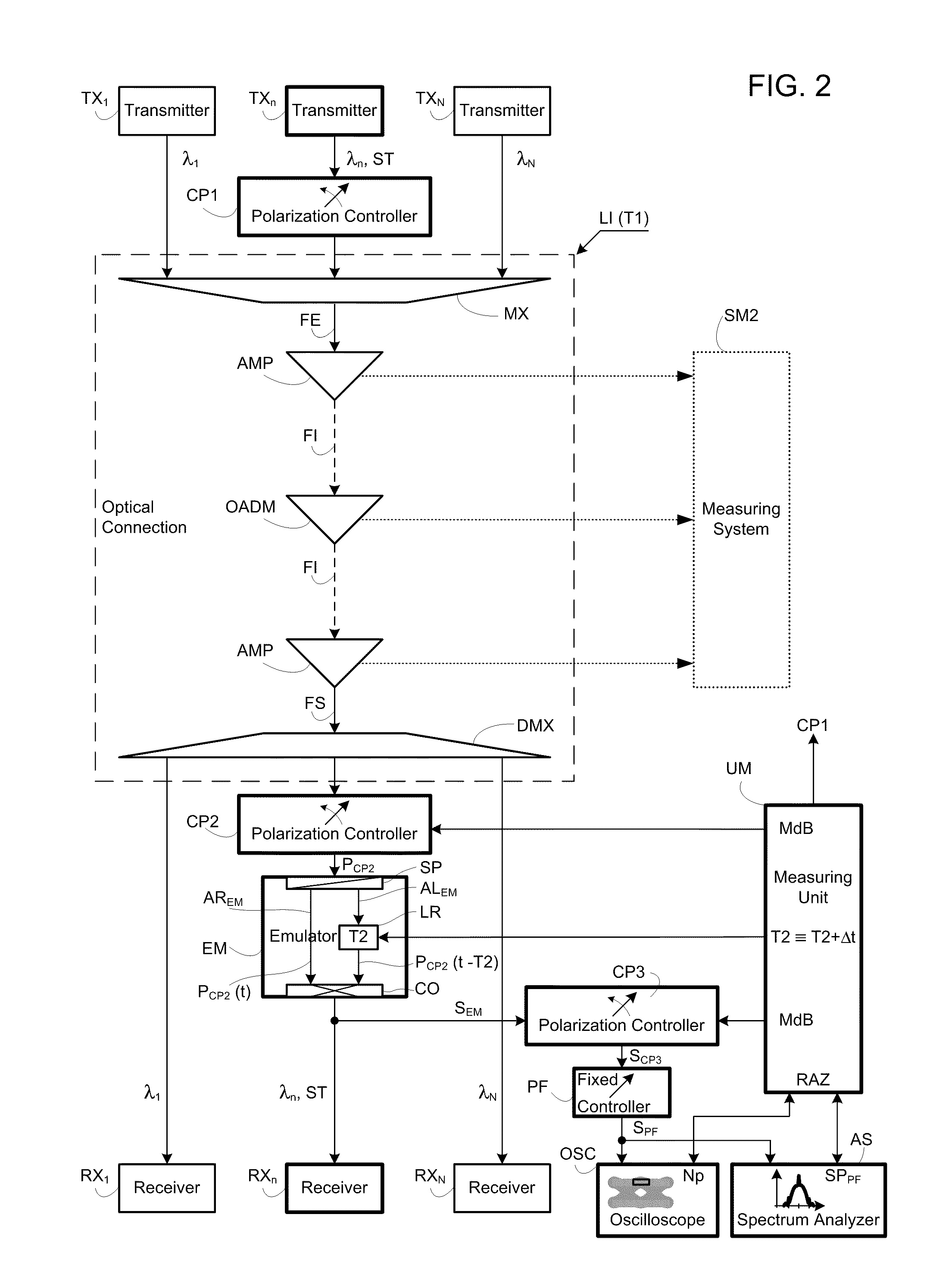
[0066]Referring to FIG. 2, the measuring system is used for measuring a differential group delay T1 in an optical fiber connection LI of wavelength division multiplexing type WDM and transmitting several optical signals respectively from transmitters TX1 to TXN, also called as transponders, to respective receivers RX1 to RXN. Signals with different wavelengths outgoing from the transmitters have undergone a phase shift keying modulation BPSK or DPSK with two phase states. The modulated signals are injected into the connection LI by input ports of a multiplexer MX to be multiplexed therein.

[0067]The connection LI is for instance composed of a first optical fiber FE transmitting the multiplexed modulated signals, then intermediate optical fibers FI and a last optical fiber FS linked to the input port of a demultiplexer DMX. The optical fibers FE, FI and FS are interconnected by optical amplifiers AMP and one or more channel insertion and extraction components OADM marking out the conn...


PUM


Abstract

The differential group delay is measured in an optical fiber connection for an optical signal undergoing a phase modulation BPSK or DPSK by a digital signal at a given rate. A polarization controller at an emerging end of the connection scans polarization states of the modulated optical signal. An emulator iteratively introduces an additional delay in the modulated optical signal emerging from the connection and combines the delayed modulated optical signal and the non delayed modulated optical signal which are both polarized along two orthogonal axes into a resulting optical signal. A polarization controller and a fixed polarizer select a polarization state in the resulting optical signal along one of bisecting lines of the orthogonal axes into a linearly polarized signal. An eye diagram or a spectrum of the polarized signal is acquired by a digital oscilloscope or an optical spectrum analyzer to determine the differential group delay.

Description

RELATED APPLICATIONS[0001]The present application is based on, and claims priority from, French Application Number 0858068, filed Nov. 27, 2008, the disclosure of which is hereby incorporated by reference herein in its entirety.BACKGROUND OF THE INVENTION[0002]1. Field of the Invention[0003]The present invention relates to measuring differential group delay in an optical fiber connection.[0004]The invention finds applications particularly in the fields of telecommunications and optical fiber metrology. In particular, it is used for qualifying an optical fiber connection for the recipe of high rate and long-range wavelength division multiplexing (WDM) optical transmission systems with binary phase shift key (BPSK) or differential phase shift key (DPSK) modulation.[0005]2. Description of the Prior Art[0006]In an optical fiber transmission system, the whole connection, including line fiber sections and chromatic dispersion compensation fiber sections, as well as various elements of the...

Claims


Application Information

Patent Timeline
IPC IPC(8): H04B10/08H04B10/077
CPCH04B10/0775G01M11/33
Inventor PINCEMIN, ERWANHUI BON HOA, DANIELGAVIGNET, PAULETTEDOURTHE, CHRISTIAN
Owner FRANCE TELECOM SA
Why Eureka
Try Eureka