Methods for determining a volumetric ratio of a material to the total materials in a mixing vessel

a technology of volumetric ratio and mixing vessel, which is applied in the direction of sealing/packing, well accessories, instruments, etc., can solve the problems of affecting the quality of the output slurry, the time-lag in the response of the water and cement control loop, and the inability of densitometers to measure the output slurry density, etc., to achieve tighter control over the relative volumes of materials and reduce the overall cost of the process

Active Publication Date: 2009-07-28
HALLIBURTON ENERGY SERVICES INC
View PDF64 Cites 15 Cited by
  • Summary
  • Abstract
  • Description
  • Claims
  • Application Information

AI Technical Summary

Benefits of technology

[0010]A need therefore exists for a control system capable of controlling the output flowrate and composition of a mixing process without needing to control or measure the output density of the process. Further, it is desirable to reduce the lag-time of the control system, allowing the process to be monitored and controlled in real time with more accuracy and precision. It is also desirable that the control system be capable of more robustly accounting for disturbances, nonlinearities, and noise that may occur in the mixing process.Methods of Determining a Volumetric Ratio of a Material to the Total Material in a Mixing Vessel
[0012]The estimated volume of a material to total materials in a mixing vessel may be determined using a volumetric ratio observer comprising a feedback loop. The volumetric ratio observer advantageously provides for filtered, zero-lag estimations of the actual volumetric ratios within the mixing vessel in a manner that accounts for unwanted disturbances in the system. By way of example, the materials being combined in the mixing vessel may be dry cement and water, and the slurry formed therein may be pumped down a wellbore during a well cementing process. Knowing the relative volumes inside the mixing vessel at any time and thus the relative volumes of the cement and water being pumped downhole may be very useful.
[0013]The volumetric ratio observer may also be employed to estimate the volumetric ratios of the components in two or more mixing vessels in series that are separated by weirs or any other channeling devices that allow fluid to pass from one vessel to the next. The volumetric ratio observer desirably may be used in a control system of such a mixing process where the density of the slurry mixture is unavailable. It may also be employed to control the mixing process even if the densities of the materials being mixed are near the same value such that a densitometer cannot clearly differentiate between them. The volumetric ratio observer allows the mixing process to be controlled volumetrically, providing for tighter control over the relative volumes of the materials in the mixing vessels. As a result, the process may be optimized such that the overall cost of the process is minimized.
[0015]As described previously, the physical system, i.e., the mixing process, may be affected by nonlinearities. In particular, the feedback of the physical system may be nonlinear, making it difficult to control. To overcome this problem, a virtual system may be simulated in real-time, wherein the virtual system i.e., the system “seen” by the control system, represents the physical dynamics without the nonlinear physical system feedback. The physical system may be controlled with reference to this virtual system by simply using a proportional controller, resulting in more stable eigenvalue behavior than if the physical system were controlled by a PI or PID controller.

Problems solved by technology

However, this type of control system has a major drawback in that the response of the water and cement control loops are time lagged.
Another drawback of this control system is that often no densitometer is available to measure the output slurry density, or the output slurry density is ill-conditioned to be used as a control variable (i.e., the value of the density of one component being mixed is very close to the value of the density of the other component being mixed in a two-component system).
Using a PI or a PID control system to overcome the physical system nonlinearity results in eigenvalue migration.
Unfortunately, the system is a coupled system in that different portions of the system depend upon each other.
Thus, fine tuning the control system is typically impossible to accomplish due to the differing time- or frequency-domain responses of the different portions of the system.
In addition to these limitations, the mixing process often experiences disturbances that can lead to inaccuracies in the measurements of the process.
Such disturbances include oscillations in the height of the fluid in the mixing vessel, particularly when the mixing vessel is in motion such as in a ship-based mixing process.
Another disturbance commonly encountered is that one material, e.g., the dry cement, may become plugged in the pipe being fed to the mixing vessel such that a significant amount of air is required to force the material into the mixing vessel.
However, note that the present application may disclose multiple embodiments, and not all of the statements in this section necessarily relate to all of those embodiments.
In particular, the feedback of the physical system may be nonlinear, making it difficult to control.

Method used


Image

  • Methods for determining a volumetric ratio of a material to the total materials in a mixing vessel
  • Methods for determining a volumetric ratio of a material to the total materials in a mixing vessel
  • Methods for determining a volumetric ratio of a material to the total materials in a mixing vessel

Examples


examples

[0101]The invention having been generally described, the following examples are given as particular embodiments of the invention and to demonstrate the practice and advantages thereof. It is understood that the examples are given by way of illustration and are not intended to limit the specification or the claims to follow in any manner.

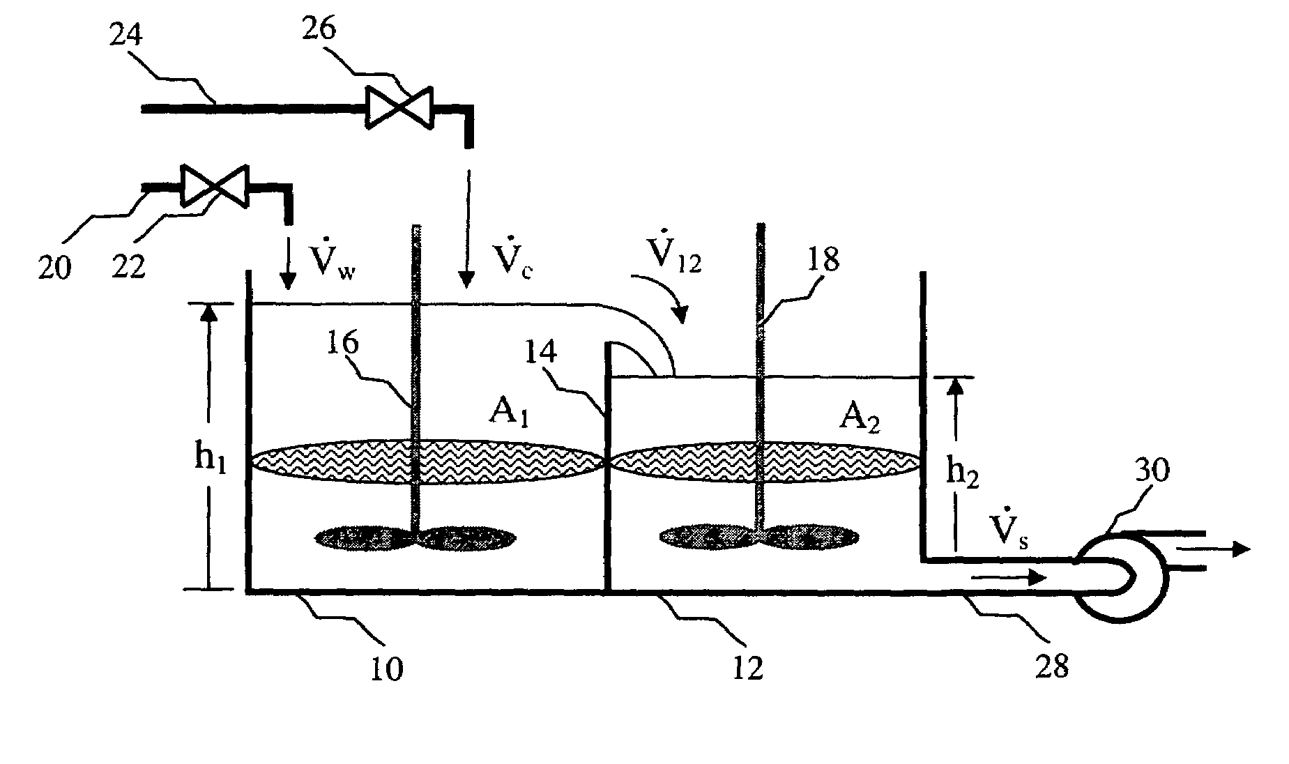
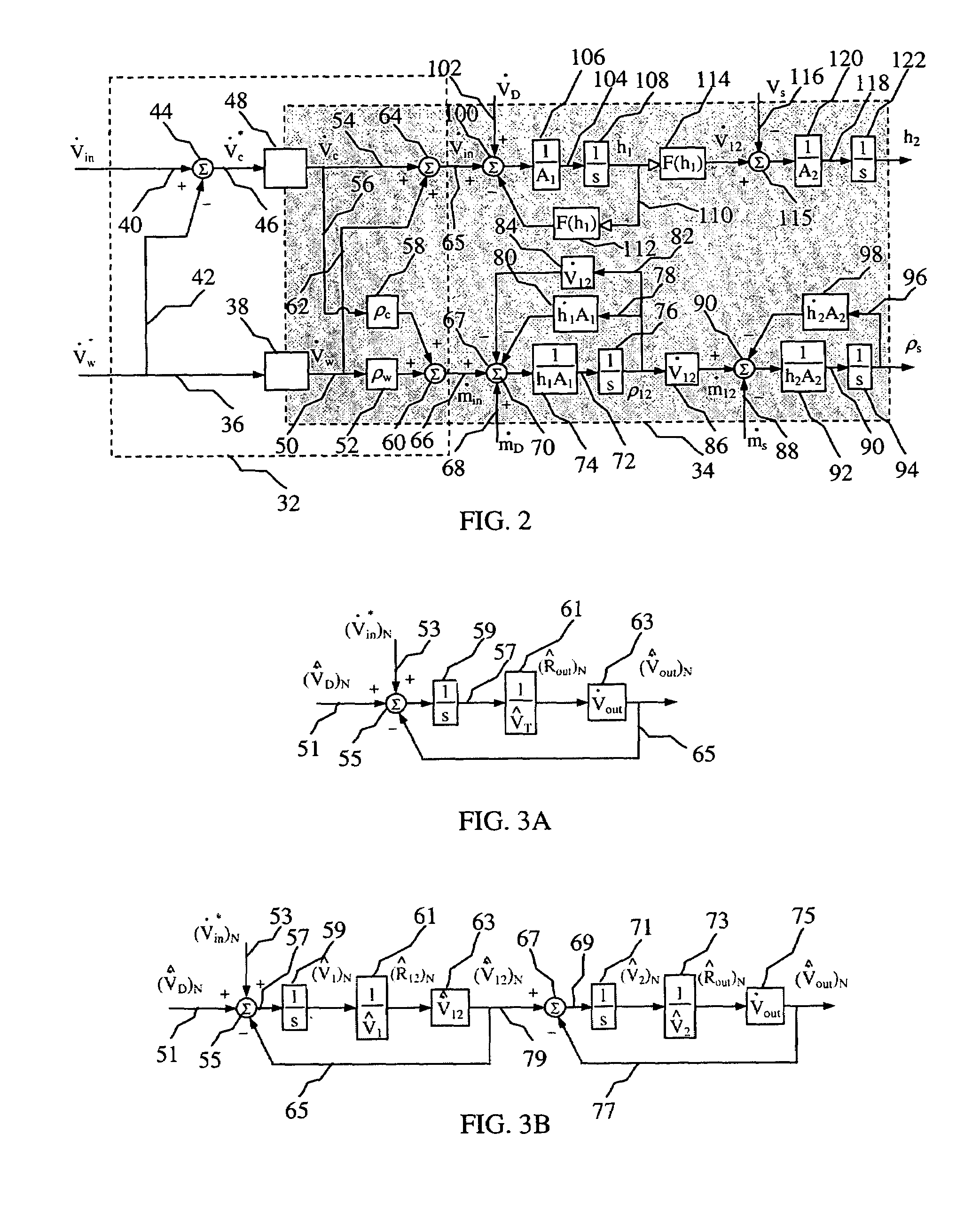
[0102]The mixing apparatus shown in FIG. 1 was assembled and operated using the embodiment of the control scheme shown in FIG. 6. Various parameters of the mixing process were determined and plotted as a function of time in FIG. 10. More specifically, line 550, labeled as the slurry recirculation density, represents the change in the measured slurry density in the first vessel. Line 552, labeled as the Ve_density represents the change in the density as given by the volumetric ratio observer with active disturbance decoupling. Line 554, labeled as the tub level, represents the change in the height of the slurry in the second vessel. Line 556, labeled ...


PUM

PropertyMeasurementUnit
timeaaaaaaaaaa
volumeaaaaaaaaaa
heightaaaaaaaaaa

Abstract

Methods are provided for determining an estimated volumetric ratio of a material to total materials in a mixing vessel. In various embodiments, the methods may comprise: summing a commanded input flowrate of the material and a volumetric disturbance flowrate of the material being fed to the mixing vessel; estimating the output flowrate of the material exiting the mixing vessel; negatively feeding back the estimated output flowrate of the material to obtain an estimated volumetric rate of change of the material in the mixing vessel; and integrating the estimated volumetric rate of change of the material to compute the estimated volumetric ratio of the material to the total materials in the mixing vessel.

Description

BACKGROUND AND SUMMARY OF THE INVENTIONS[0001]The present invention generally relates to process control, and more particularly to methods of estimating the volumetric ratio of a material to the total materials in a mixing vessel.[0002]The following applications filed concurrently herewith are not necessarily related to the present application, but are incorporated by reference herein in their entirety:[0003]“Systems for Determining a Volumetric Ratio of a Material to the Total Materials in a Mixing Vessel” (U.S. application Ser. No. 11 / 323,323, filed simultaneously with the effective filing date of the present application);[0004]“Systems for Volumetrically Controlling a Mixing Apparatus” (U.S. application Ser. No. 11 / 323,322, filed simultaneously with the effective filing date of the present application); and[0005]“Methods of Volumetrically Controlling a Mixing Apparatus,” (U.S. application Ser. No. 11 / 323,324, filed simultaneously with the effective filing date of the present appl...

Claims


Application Information

Patent Timeline
Patent Type & Authority Patents(United States)
IPC IPC(8): G05D11/02B01F15/04
CPCG05D11/133
Inventor DYKSTRA, JASON D.BORGSTADT, JUSTIN A.
Owner HALLIBURTON ENERGY SERVICES INC
Why Eureka
Try Eureka