
Apparatus and method for detecting obstacle adaptively to vehicle speed

a technology of adaptive vehicle speed and apparatus, applied in the direction of instruments, using reradiation, transportation and packaging, etc., can solve the problems of difficult temporally synchronizing sensors, large amount of expensive equipment, etc., and achieve the effect of increasing the speed of the vehicl

Active Publication Date: 2014-07-31
ELECTRONICS & TELECOMM RES INST
View PDF4 Cites 53 Cited by
  • Summary
  • Abstract
  • Description
  • Claims
  • Application Information

AI Technical Summary

Benefits of technology

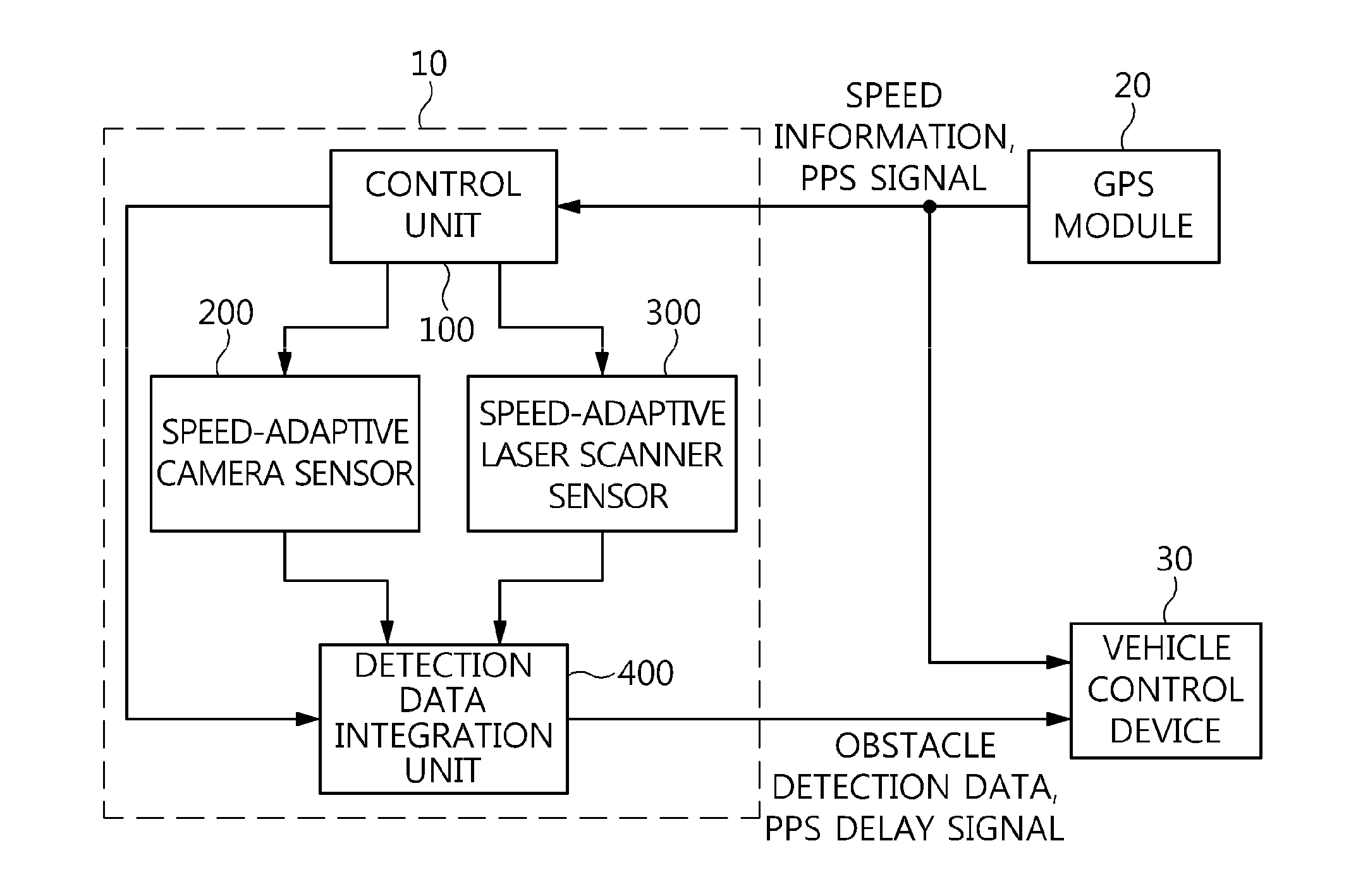
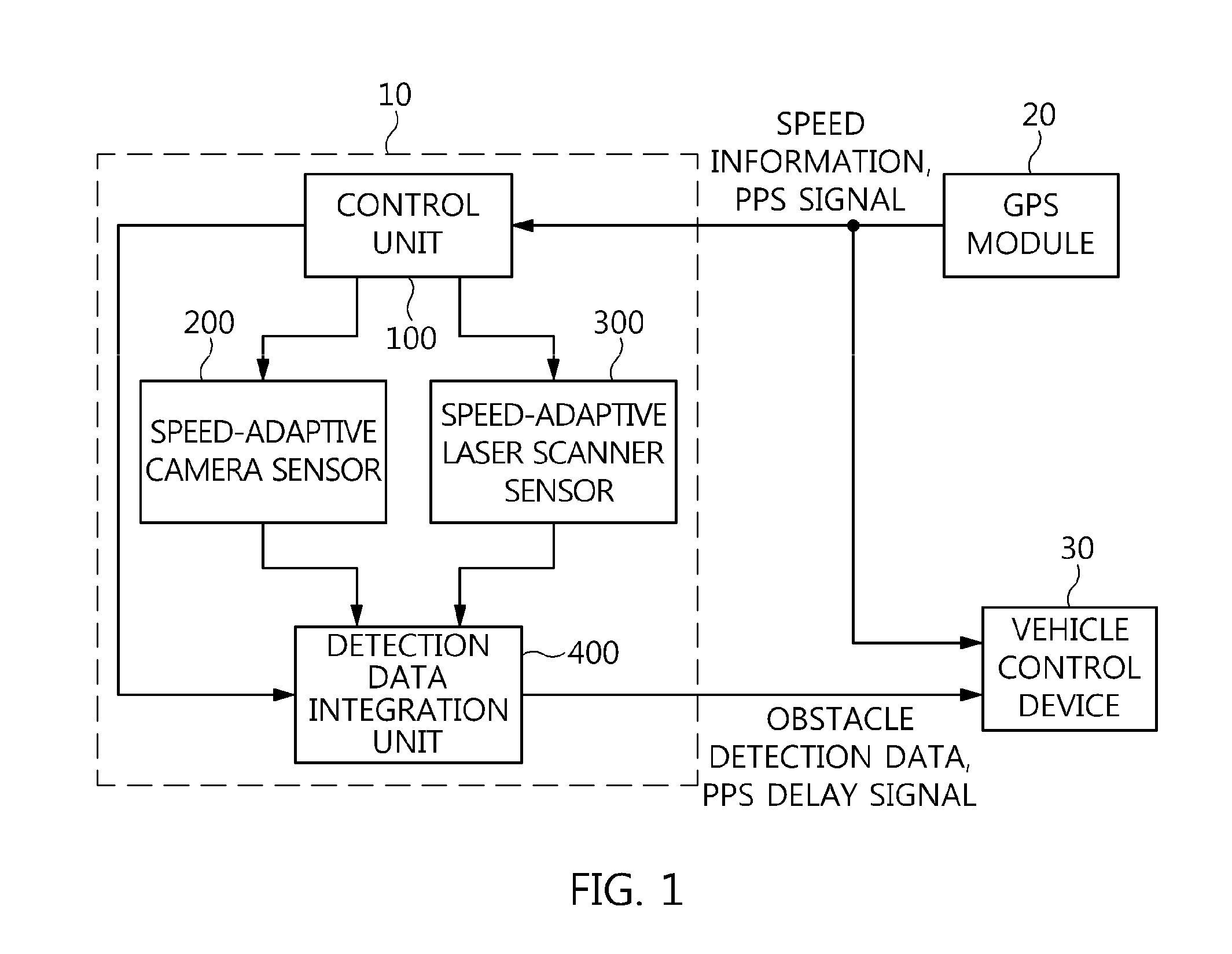
The present invention aims to improve obstacle detection in vehicles by reducing the detection region based on the vehicle speed. Another objective is to generate obstacle detection data by integrating data from heterogeneous sensors and outputting information about delay time for synchronization between the sensors. This facilitates the operation of another system and allows for the temporal synchronization of the sensors.

Problems solved by technology

Furthermore, since a single type of sensors are unable to deal with all types of driving environments, various types of sensors are being used or a technology into which heterogeneous sensors have converged is being used.
In the convergence of heterogeneous sensors, it is difficult to temporally synchronize the sensors due to the differences in the data processing and output results of the sensors, and a lot of expensive equipment should be used due to various types of driving environments.
However, in conventional technologies for detecting an object around a vehicle, such as the technology disclosed in U.S. Patent Application Publication No. 2010 / 0328644, a scheme for improving obstacle detection response speed or a scheme for providing temporal synchronization in order to integrate the detection data of heterogeneous sensors is not taken into consideration at all.

Method used


Image

  • Apparatus and method for detecting obstacle adaptively to vehicle speed
  • Apparatus and method for detecting obstacle adaptively to vehicle speed
  • Apparatus and method for detecting obstacle adaptively to vehicle speed

Examples


Embodiment Construction

[0033]An apparatus and method for detecting an obstacle adaptively to vehicle speed according to the present invention will be described with reference to the accompanying drawings. Prior to the following detailed description of the present invention, it should be noted that the terms and words used in the specification and the claims should not be construed as being limited to ordinary meanings or dictionary definitions. Meanwhile, the embodiments described in the specification and the configurations illustrated in the drawings are merely examples and do not exhaustively present the technical spirit of the present invention. Accordingly, it should be appreciated that there may be various equivalents and modifications that can replace the examples at the time at which the present application is filed.

[0034]The configuration and operation of an apparatus for detecting an obstacle adaptively to vehicle speed according to the present invention will be described with reference to FIGS. ...


PUM


Abstract

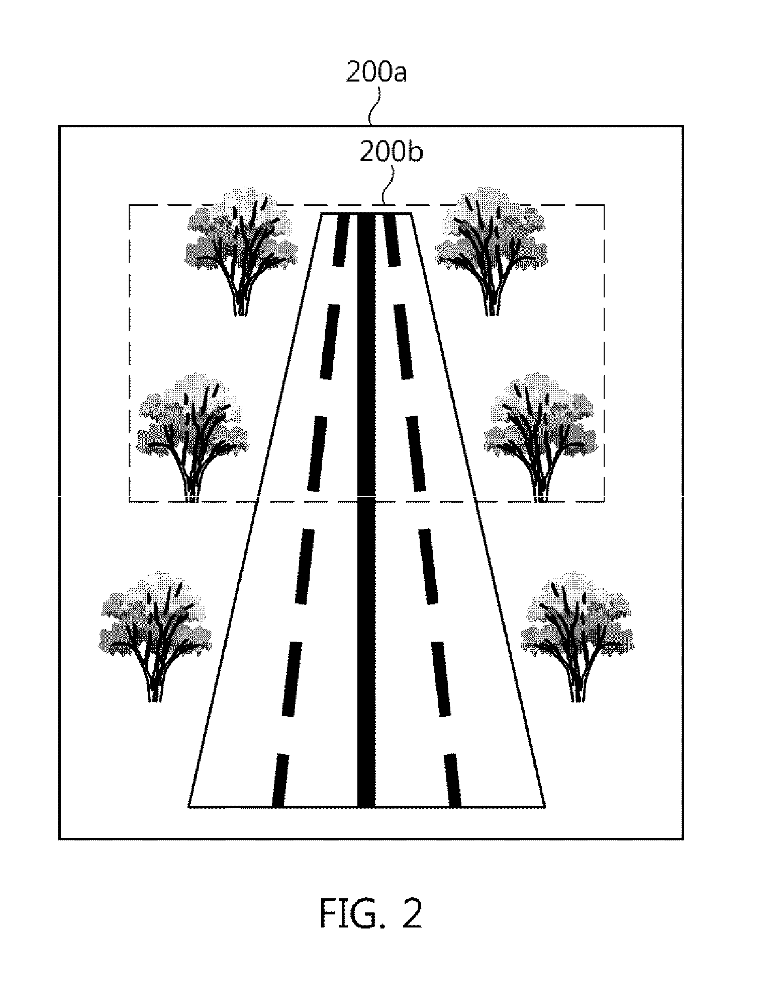
Disclosed herein are an apparatus and method for detecting an obstacle adaptively to vehicle speed. The apparatus includes a control unit, a speed-adaptive camera sensor, a speed-adaptive laser scanner sensor, and a detection data integration unit. The control unit receives information about the speed of a vehicle and a Pulse Per Second (PPS) signal from a Global Positioning System (GPS) module. The speed-adaptive camera sensor adjusts the range of a detection region based on the information about the speed of the vehicle, and generates first detection data on an object. The speed-adaptive laser scanner sensor adjusts the range of the angle of the field of view of a laser scanner based on the information about the speed of the vehicle, and generates second detection data on the object. The detection data integration unit outputs obstacle detection data.

Description

CROSS REFERENCE TO RELATED APPLICATION[0001]This application claims the benefit of Korean Patent Application No. 10-2013-0011459, filed on Jan. 31, 2013, which is hereby incorporated by reference in its entirety into this application.BACKGROUND OF THE INVENTION[0002]1. Technical Field[0003]The present invention relates generally to an apparatus and method for detecting an obstacle adaptively to vehicle speed, which are capable of detecting an obstacle in front of a vehicle to assist in safe driving and, more particularly, to an apparatus and method for detecting an obstacle adaptively to vehicle speed, which can adjust obstacle detection response speed by varying a detection region within which an obstacle is detected in front of a vehicle based on the speed of the vehicle, and can also integrate detection data generated by a plurality of heterogeneous sensors by providing a synchronization signal to the plurality of sensors that generate detection data on obstacles.[0004]2. Descrip...

Claims


Application Information

Patent Timeline
Patent Type & Authority Applications(United States)
IPC IPC(8): B60R1/00
CPCB60R1/002B60W30/095B60W2050/0075B60W2520/10B60W2556/50B60W2420/408B60W2420/403G01S17/93G01S17/50G01S19/01
Inventor CHOI, HYUN-KYUNSUNG, KYUNG-BOKKWAK, DONG-YONGLIM, DONG-SUN
Owner ELECTRONICS & TELECOMM RES INST
Learn More