Crankcase ventilation filter systems; components; features; and, mehtods of assembly and use

Active Publication Date: 2014-08-07
DONALDSON CO INC
View PDF7 Cites 26 Cited by
  • Summary
  • Abstract
  • Description
  • Claims
  • Application Information

AI Technical Summary

Benefits of technology

[0013]The first and second vertically spaced seals or seal member can be, independently of one another, be a radially directed seal, or an axially directed seal, or can include segments of both. The two seals can be used to provide advantageous positioning of the cartridge, within an assembly, and to help ensure that the cartridges are a proper cartridge for the assembly. Indeed, the assembly can be configured so that if the two seals are not properly in place, the service provider will immediately know that the cartridge is the wrong one for the assembly. Also, the assembly can be configured so that if the cartridge with the appropriate seal is not in place, the service provider will immediately know this, when an attempt is made to lock close the access cover.

Problems solved by technology

Indeed, the assembly can be configured so that if the two seals are not properly in place, the service provider will immediately know that the cartridge is the wrong one for the assembly.

Method used


Image

  • Crankcase ventilation filter systems; components; features; and, mehtods of assembly and use
  • Crankcase ventilation filter systems; components; features; and, mehtods of assembly and use
  • Crankcase ventilation filter systems; components; features; and, mehtods of assembly and use

Examples


first embodiment

II. A First Embodiment

FIGS. 1-27

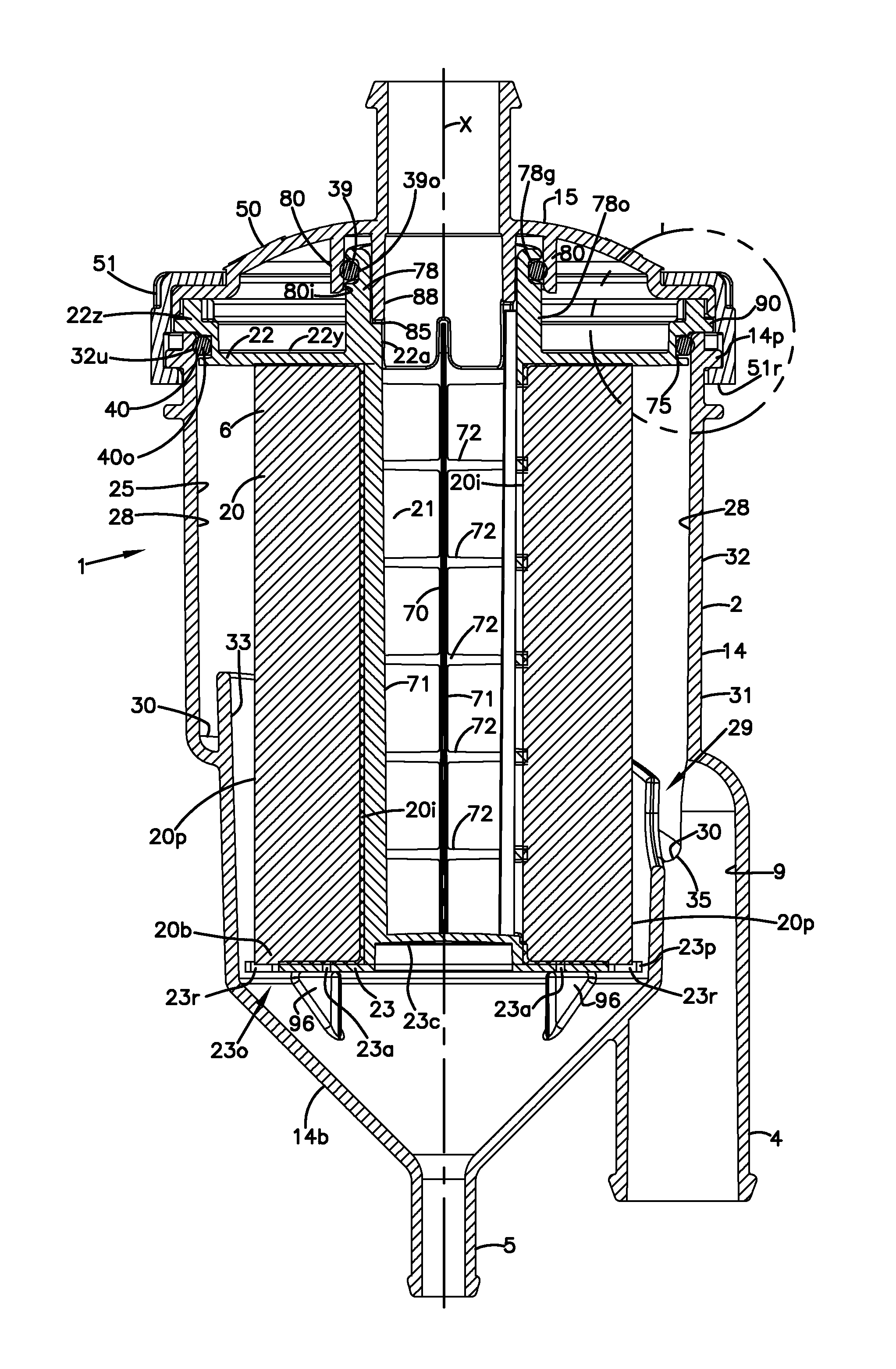
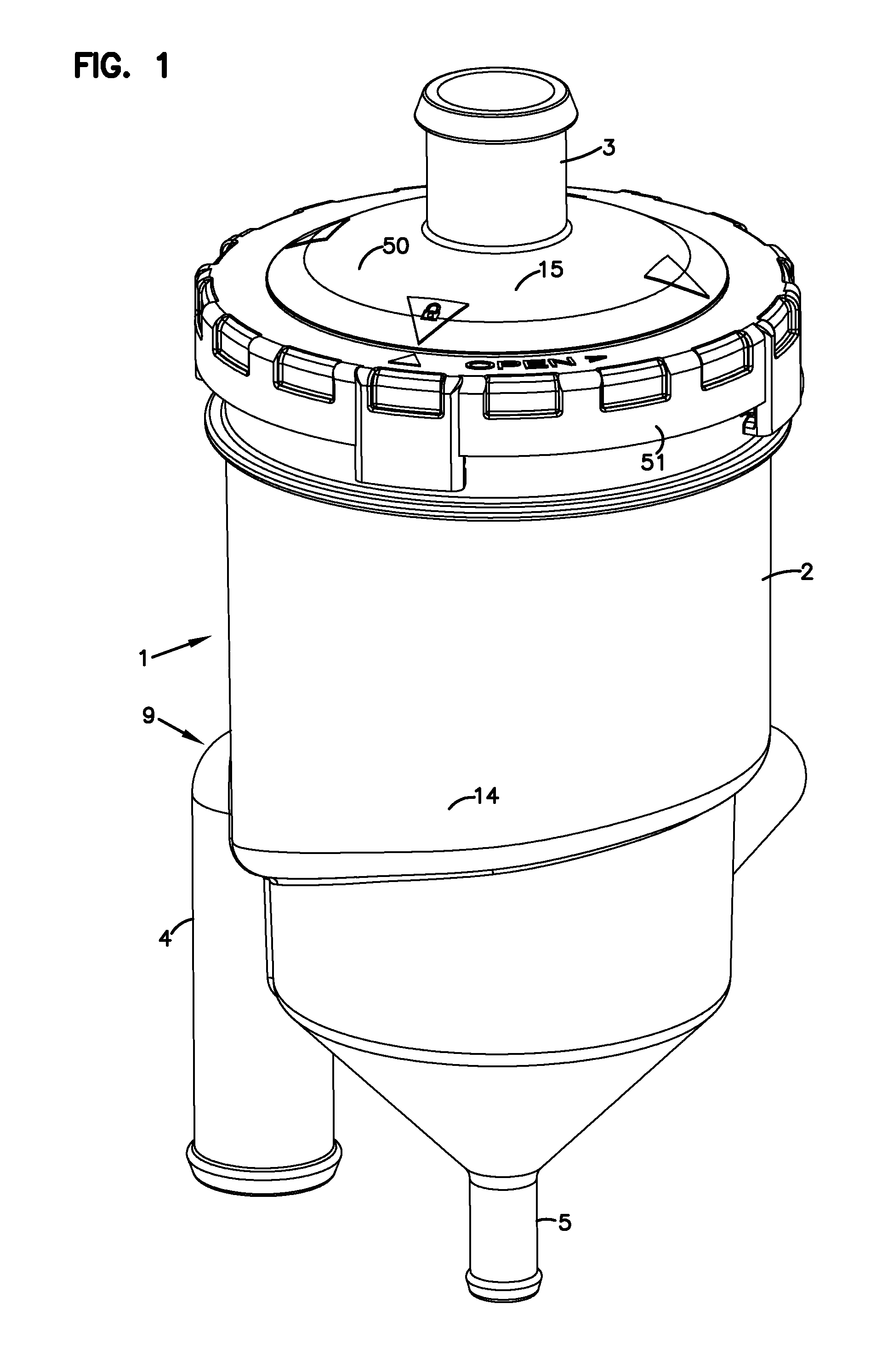
[0083]A first embodiment of a crankcase ventilation filter assembly according to the present disclosure is depicted in FIGS. 1-27. Referring first to FIG. 1, at 1 the crankcase ventilation filter assembly is generally depicted. The assembly 1 generally comprises a housing 2 having: a gas flow inlet arrangement 3, gas flow outlet arrangement 4, and a coalesced liquid (oil) drain outlet arrangement 5. Within the housing 2 is generally depicted a serviceable filter cartridge 6 (not shown in FIG. 1 see the cross-sectional views of FIGS. 5 and 6; and, the cartridge views of FIGS. 23-26, discussed below).

[0084]In general operation, engine blowby or crankcase ventilation filter gases from an engine system with which the assembly 1 is used, are directed into the housing 2 through the gas flow inlet arrangement 3. Within the housing 2, the gases are passed into filter media of an internally received serviceable filter cartridge 6. Within the media, the gases a...

second example embodiment

III. A Second Example Embodiment

FIGS. 28-31

[0183]In FIGS. 28-31, a second embodiment of an assembly including features generally in accord with the present disclosure is depicted. In FIG. 28, an exploded view of assembly 101 is depicted. Assembly 101 includes a housing 102 comprising housing base 114 and service cover 115; the service cover comprising central portion 115a and a mounting ring 115b. The assembly 101 includes a gas flow inlet arrangement 103, a gas flow outlet arrangement 104, liquid drain arrangement 105 and a mounting pad arrangement 118 including mounting pads 118x.

[0184]The mounting base 114 includes an upper end 114e with receiver recesses 114r therein. Also, the upper end 114e of the housing base 114 includes projections 114p thereon, to be engaged by lock members 115x on the mounting ring 115b when the mounting ring 115b is appropriately tightened.

[0185]In FIG. 28, the cartridge 106 is depicted but without the media thereon. The media can be positioned as is me...

third embodiment

IV. A Third Embodiment

[0191]In the embodiment of FIGS. 1-27, and in the second embodiment of FIGS. 28-31, the access cover in each instance was configured so that the mounting ring thereon rotated between locked and unlocked positions by a non-threaded rotational engagement interactions between portions of a mounting ring and on the housing. A threaded engagement, therefore, was not used. It is noted that many of the principles described herein can be applied in a system in which a threaded engagement is used. Indeed a threaded arrangement could have been used with the previously described embodiments. This will be understood, for example, from the embodiment depicted in FIGS. 32 and 33.

[0192]It also noted that in the first embodiment of FIGS. 1-27 and the second embodiment of FIGS. 28-31, the cartridge in each instance was configured so that a central preform or spool could be used around which the media was coiled between two end pieces. This, generally, required the seal arrangem...


PUM

PropertyMeasurementUnit
angleaaaaaaaaaa
angleaaaaaaaaaa
angleaaaaaaaaaa

Abstract

Crankcase ventilation filter assemblies are described and shown. Components, features and methods of assembly and use are described. Many of the principles relate to preferred cartridge configurations for engagement with selected housings. Selected optional features described can be used to provide indication to a service provider that a proper cartridge is not positioned appropriately in the housing for use.

Description

CROSS-REFERENCE TO RELATED APPLICATIONS[0001]The present application includes the disclosure of, with edits; U.S. provisional 61 / 503,063 filed Jun. 30, 2011. The complete disclosure of U.S. 61 / 503,063 is incorporated herein by reference.[0002]The present application also includes the disclosure of U.S. provisional 61 / 664,340 filed Jun. 26, 2012. The complete disclosure of U.S. 61 / 664,340 is incorporated herein by reference.[0003]The invention disclosed herein is also implemented in one of the embodiments described in U.S. Ser. No. 61 / 665,501 filed Jun. 28, 2012. The complete disclosure of U.S. Ser. No. 61 / 665,501 is incorporated herein by reference.[0004]A claim of priority is made to each of U.S. Ser. Nos. 61 / 503,063; 61 / 664,340; and, 61 / 665,501, to the extent appropriate.[0005]This application is being filed on 29 Jun. 2012, as a PCT International Patent application in the name of Donaldson Company, Inc., a U.S. national corporation, applicant for the designation of all countries ...

Claims


Application Information

Patent Timeline
Patent Type & Authority Applications(United States)
IPC IPC(8): B01D46/24
CPCB01D46/2411F01M13/04F01M2013/0438B01D2265/021B01D2279/35B01D2271/027B01D2271/022B01D2265/026B01D2265/024
Inventor WOOD, ROBERTWILLEMS, GERT
Owner DONALDSON CO INC
Why Eureka
Try Eureka