Force sensitive touch sensor

Active Publication Date: 2014-08-07
SONY CORP
View PDF4 Cites 19 Cited by
  • Summary
  • Abstract
  • Description
  • Claims
  • Application Information

AI Technical Summary

Benefits of technology

[0013]According to another aspect of the present invention, a display comprising the sensor described above is provided. The insulating support layer comprises a window layer of the display. Furthermore, the insulating support layer may comprise a flexible layer arranged below the window layer of the display. Due to the transparency of the graphene, the sensor may be arranged in an upper side of a display, for example a liquid crystal display (LCD), without disturbing an optical output of the display.
[0014]According to another aspect of the present invention, a method of using the above-described sensor is provided. According to the method, a touch position of a user touching the sensor is determined based on the capacitance which varies in response to a change in a surrounding environment of the electrically conductive sensor structure, and a touch force of the user touching the sensor is determined based on the resistance and the touch position. The insulating support layer may provide different resiliences at different positions. Therefore, the resistance varying in response to a force being applied to the insulating support layer may vary differently depending on the touch posit

Problems solved by technology

However, it may be brittle and may crack and is furthermore expensive due to the cost of indium.
This may disturb a clean

Method used


Image

  • Force sensitive touch sensor
  • Force sensitive touch sensor
  • Force sensitive touch sensor

Examples


Embodiment Construction

[0029]In the following, exemplary embodiments of the present invention will be described in more detail. It has to be understood that the following description is given only for the purpose of illustrating the principles of the invention and is not be taken in a limiting sense. Rather, the scope of the invention is defined only by the appended claims and is not intended to be limited by the exemplary embodiments hereinafter.

[0030]It is to be understood that the features of the various exemplary embodiments described herein may be combined with each other unless specifically noted otherwise.

[0031]Same reference signs in the various drawings and the following description refer to similar or identical components.

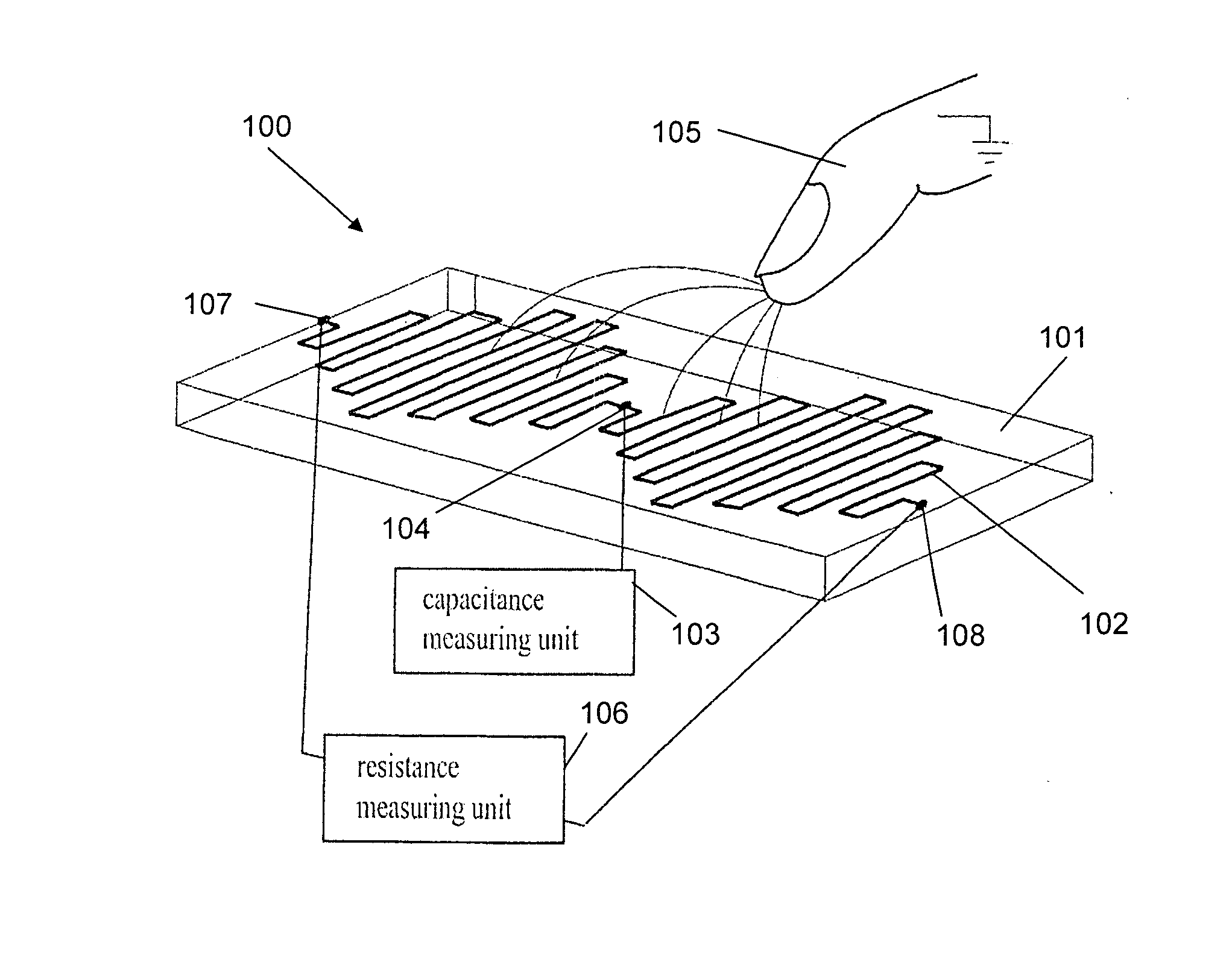
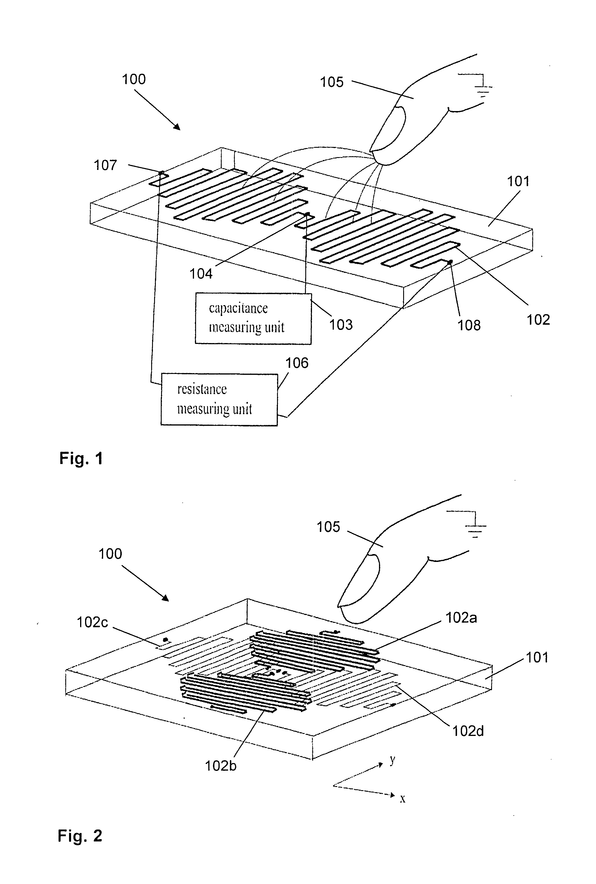
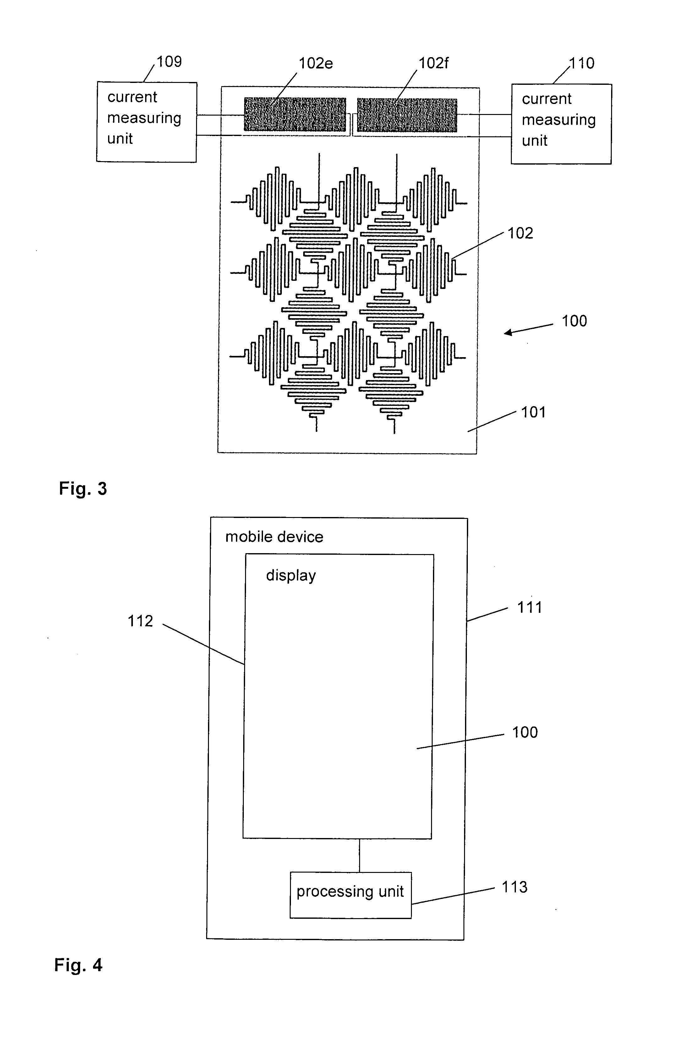
[0032]FIG. 1 shows a sensor 100 comprising an insulating support layer 101 and an electrically conductive sensor structure 102. The electrically conductive sensor structure 102 is arranged on an upper side of the insulating support layer 101. The electrically conductive sensor ...


PUM


Abstract

A force sensitive touch sensor (100) is provided. The sensor (100) comprises an insulating support layer (101) and an electrically conductive sensor structure (102). The electrically conductive sensor structure (102) comprises a piezoresistive material and is configured to provide a resistance varying in response to a force being applied to the insulating support layer (101). The piezoresistive material comprises graphene.

Description

FIELD OF THE INVENTION[0001]The present application relates to a sensor comprising an insulating support layer and an electrically conductive sensor structure which is configured to provide a resistance varying in response to a force applied to the sensor. The present application relates especially to a sensor in which the electrically conductive sensor structure comprises a graphene. The present application relates furthermore to a display and a touch sensitive user interface comprising the force sensitive touch sensor and to a device comprising the touch sensitive user interface. Finally, the present application relates to methods for operating the force sensitive touch sensor.BACKGROUND OF THE INVENTION[0002]Touch sensors are known in the art for controlling devices via a user interface or a man machine interface. Traditionally, touch sensors are adapted to detect a touch position in a two-dimensional way. Especially consumer products, for example mobile telephones, mobile naviga...

Claims


Application Information

Patent Timeline
IPC IPC(8): G01L1/18G01L1/14
CPCG01L1/14G01L1/18G06F3/041G06F3/0421G06F3/0443G06F3/0445
Inventor ABERG, PETERKLINGHULT, GUNNAR
Owner SONY CORP
Why Eureka
Try Eureka