Flexible jack

A jack and flexible technology, applied in the direction of lifting devices, etc., can solve the problems of load loss, small output, inaccurate output measurement, etc., and achieve the effects of improving technology and test quality, clear force transmission path, and easy operation

Pending Publication Date: 2019-03-29
CHANGJIANG RIVER SCI RES INST CHANGJIANG WATER RESOURCES COMMISSION
View PDF0 Cites 0 Cited by
  • Summary
  • Abstract
  • Description
  • Claims
  • Application Information

AI Technical Summary

Problems solved by technology

[0004] In order to solve the problem that the hydraulic (hydraulic) steel sleeper used in the existing rock mechanics test is not fully flexible, the contact area between the hydraulic steel sleeper and the compressed rock mass or single-layer rigid plate increases with the increase of the output force in the early stage of force output. In the later stage, as the output force increases, the load decreases gradually, and most of the deformation cannot be recovered. Like other flexible jacks, there are problems that the output force cannot be accurately calculated, and the stroke is short and the output force is small. However, the existing rock mechanics tests are generally in the The surface of the test body is laminated with a si

Method used


Image

  • Flexible jack
  • Flexible jack
  • Flexible jack

Examples


Embodiment 1

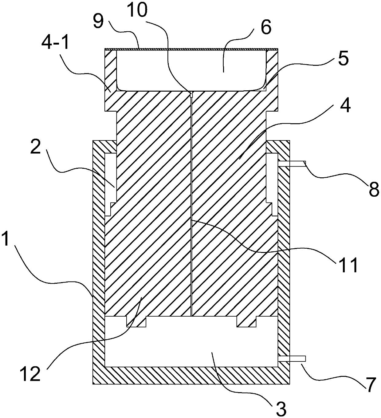
[0027] A kind of flexible jack that embodiment one provides, as Figure 1 to Figure 3Shown comprises cylinder body 1, piston rod 4 and the piston 12 that places in cylinder body 1, and its cylinder body 1 is circular, and piston 12 is circular, is provided with piston chamber in cylinder body 1, and piston chamber is covered by piston 12 The upper oil cylinder 2 and the lower oil cylinder 3 are separated, and the lower part of the lower oil cylinder 3 is provided with a pressurizing oil nozzle 7, and the upper part of the upper oil cylinder 2 is provided with a depressurizing oil nozzle 8, and the pressurizing oil nozzle 7 and the depressurizing oil nozzle 8 extend out of the cylinder body 1. It is also used to connect with external hydraulic pipelines. The piston rod 4 is made of high-strength steel, one end is connected to the piston 12, and the end away from the piston 12 protrudes from the piston chamber, and the end is provided with an ejection end 4- with the same sectio...

Embodiment 2

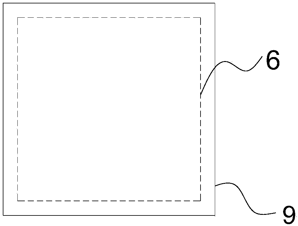
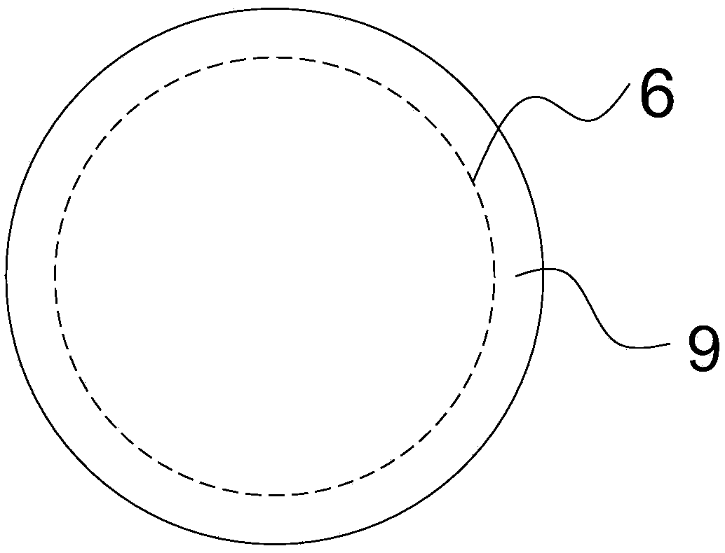
[0032] A kind of flexible jack that embodiment 2 provides, the structure of its cylinder 1, piston rod 4 and piston is the same as embodiment 1, and its difference is that no flexible chamber is provided at the pushing end of the piston rod, and a flexible cavity is provided at the bottom of cylinder 1. The lower bump 1-1 with the same width as the piston 12 has an upward flexible cavity 5 on the bottom surface of the lower bump 1-1, and a flexible pressure-bearing bag matching the shape of the cavity is arranged in the flexible cavity 5 6. A flexible pressure-bearing pad 9 is provided at the mouth of the flexible cavity 5 where the flexible pressure-bearing bladder 6 is located. The mouth of the cavity is fixedly connected; the flexible pressure-bearing bag 6 communicates with the lower oil cylinder 3 through the oil hole 11 arranged on the central axis of the bottom plate of the cylinder body 1, and the non-corrosive hydraulic oil is filled into the flexible pressure-bearing ...


PUM


Abstract

The invention provides a flexible jack. The jack comprises a cylinder, a piston rod and a piston; the piston divides the cylinder into an upper oil cylinder and a lower oil cylinder, a pressure oil nozzle is arranged on the lower portion of the lower oil cylinder, and a pressure relief oil nozzle is arranged on the upper portion of the upper oil cylinder; a flexible cavity is formed in the portion, away from the ejection end of the piston or on a lower convex block at the bottom of the cylinder, of the piston rod, the flexible cavity is internally provided with a flexible pressure-bearing capsule matched with the cavity shape, a flexible pressure-bearing capsule mat is arranged on the portion, located at an opening of the flexible cavity, of the flexible pressure bearing capsule, the areaof the flexible pressure-bearing capsule mat is equal to the effective output area of the lower oil cylinder, and the flexible pressure-bearing capsule mat is fixedly connected with the opening of theflexible cavity; the flexible pressure-bearing capsule is communicated with the lower oil cylinder through an oil through hole. Accordingly, a force transferring path is definite, the problems that in an existing rock mass mechanics test, a hydraulic (force) steel pillow, the flexible jack and an ordinary jack are used, rock mass stress measurement is inaccurate, compressive rock mass or rigid plate stress is nonuniform, and deformation deviation exits are solved, and the rock mass mechanics test quality is improved.

Description

technical field [0001] The invention belongs to the technical field of rock and soil mechanics and engineering, and relates to loading equipment for rock mechanics tests, in particular to a flexible jack. Background technique [0002] At present, the hydraulic steel sleeper, also known as the hydraulic steel sleeper, is a loading device for rock mechanics tests. It is a flat oil cavity formed by bending and welding two thin steel plates of the same shape. The oil expands and deforms the wall of the oil chamber to squeeze the rock mass, and the contact area of ​​the hydraulic steel pillow with the compressed rock mass or single-layer rigid plate increases with the increase of the output force in the early stage of the force output, and decreases with the increase of the output force in the later stage. If the load is small, the load gradually concentrates, and the force-bearing area cannot be accurately calculated, so the obtained rock mass force is inaccurate. Since the hyd...

Claims


Application Information

Patent Timeline
IPC IPC(8): B66F3/24B66F3/25B66F3/35
CPCB66F3/24B66F3/25B66F3/35B66F2700/055B66F2700/057
Inventor 邬爱清余美万张宜虎范雷边智华陈冲熊诗湖王帅罗荣向前唐爱松庞正江李玉婕谢斌蒋志明
Owner CHANGJIANG RIVER SCI RES INST CHANGJIANG WATER RESOURCES COMMISSION
Why Eureka
Try Eureka